This chapter describes all the connectors and LEDs located on the back of the VBOB chassis.
Figure 3-1 shows the rear panel connectors with an optional DMediaPro DM5 installed.
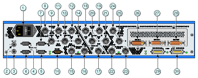
Table 3-1 lists the VBOB rear panel connectors and their functions.
Table 3-1. Rear Panel Connectors
ID # | Connector Name | Connector Function |
|---|---|---|
1. | AC plug and switch | AC power connection from chassis to power source |
2. | 8-pin mini-DIN | General purpose I/O connector #1 (reserved for future use) |
3. | General purpose I/O connector #2 (reserved for future use) | |
4. | 9-pin subminiature D | |
5. | 9-pin subminiature D | RS-422 serial port D (reserved for future use) |
6. | RS-422 serial port C (reserved for future use) | |
7. | 9-pin subminiature D | RS-422 serial port B (reserved for future use) |
8. | SD in BNC #1 | Standard-definition in #1 (link A) |
9. | SD in BNC #2 | Standard-definition in #2 (link B) |
10. | 9-pin subminiature D | |
11. | SD out BNC #1 | Standard-definition out #1 (link A) |
12. | SD out BNC #1 | Standard-definition out #1 (link A) |
13. | SD out BNC #2 | Standard-definition out #2 (link B) |
14. | SD out BNC #2 | Standard-definition out #2 (link B) |
15. | SD genlock BNC | Standard-definition genlock in BNC |
16. | SD genlock BNC | Standard-definition genlock loop-through |
17. | Timing BNC | |
18. | HD out BNC #1 | |
19. | HD out BNC #1 | High-definition out BNC #1 (link A) |
20. | HD out BNC #2 | High-definition out BNC #2 (link B) |
21. | HD out BNC #2 | High-definition out BNC #2 (link B) |
22. | ||
23. | HD genlock BNC | |
24. | HD in #1 BNC | High-definition in BNC #1 (link A) |
25. | HD in #2 BNC | High-definition in BNC #2 (link B) |
26. | DVI IN 1 | |
27. | DVI IN 0 | Digital Visual Interface (DVI) in connector #1 |
28. | DVI OUT | Digital Visual Interface (DVI) out connector #1 |
29. | LVDS A | LVDS connector |
30. | LVDS B | LVDS connector |
 | Note: The VBOB has two BNC connectors for each external HD and SD genlock source. You can use either of these connectors as an input or a loop-through. |
There are eight LEDs on the rear of the VBOB chassis, as shown in Figure 3-2. The SD, HD, genlock, and LVDS LEDs indicate the following:
SOLID - Signal present and valid
FLASHING - Signal present but unrecognizable (invalid, such as wrong video format)
OFF - No signal present
The last LED on the right indicates the processor activity. This LED should flash at a rate of about 1 Hz.

Follow these steps to connect the cables and boot the host system. See Figure 3-1 and Table 3-1 for the location and functional descriptions of the rear panel connectors.
Be sure the VBOB power switch at the back of the chassis is in the Off (O) position.
Connect one end of the power cord to the VBOB power plug and the other end of the cord to your AC power source.
Connect all other cables as applicable.
Turn the VBOB power switch to the On (-) position.
-
Note: You can find cabling instructions for a specific configuration in the user's guide provided with your VBOB-related product.