This guide provides information on mounting the SGI 1450 server in a 19-inch rack. It also provides pedestal mounting instructions (see “Installing and Removing the Pedestal Kit”).
To obtain SGI documentation on the World Wide Web, see the SGI Technical Publications Library at http://techpubs.sgi.com. Enter a keyword search, or search by title to find the information or manual you need.
 | Warning: To avoid personal injury when unpacking the server, use only a mechanical assist unit to lift it off the shipping pallet. The minimum server configuration weighs 26 kg (57 lbs); the maximum configuration weighs 45 kg (100 lbs). Do not attempt to lift or move the server by the handles on the power supplies. Use only a hand-truck or other mechanical assist unit to move the server from one location to another. |
This guide contains the following sections:
Remove the server from the packaging container and check that all accessories are included. Inspect the packaging container for evidence of mishandling during transit. If the packaging container is damaged, photograph it for reference. After removing the contents, keep the damaged container and the packing materials.
Inspect the server and accessories for damage. If the contents appear damaged, file a damage claim with the carrier immediately.
The SGI 1450 server is designed either to be mounted in a standard 19-inch rack (rack mode) or to stand upright (pedestal mode).
Table 1-1 specifies the space requirements for the SGI 1450 server system in rack mode and pedestal mode.
Table 1-1. SGI 1450 Server Physical Specifications
Specification | Rack Mode | Pedestal Mode |
|---|---|---|
Height | 4u (7 inches) | 20.75 inches (52.7 cm) |
Width | 17.5 inches (44.5 cm) | 8.6 inches (21.8 cm) |
Depth | 26.5 inches (67.3 cm) | 28.75 inches (73 cm) |
Weight | 57 lbs (26 kg), min. configuration 88 lbs (40 kg), max. configuration | 69 lbs (31 kg), min. configuration 100 lbs (45 kg), max. configuration |
Required front clearance | 3 inches (7.6 cm) (inlet air temperature <35 ˚C / 95 ˚F) | 6 inches (15 cm) (inlet air temperature <35 ˚C / 95 ˚F) |
Required rear clearance | 6 inches (15 cm) (no airflow restriction allowed) | 4 inches (10 cm) (no airflow restriction allowed) |
Required side clearance | 1 inch (2.5 cm) | N/A |
Required top clearance | N/A | 2 inches (5 cm) |
Read the following warnings and cautions before proceeding with the installation.
| Warning: You are responsible for installing an AC power disconnect for the entire rack unit. This main disconnect must be readily accessible, and it must be labeled as controlling power to the entire unit, not just to the server(s). To avoid the potential for an electrical shock hazard, you must include a third wire safety grounding conductor with the rack installation. If a server power cord is plugged into an AC outlet that is part of the rack, then you must provide proper grounding for the rack itself. If server power cords are plugged into wall AC outlets, the safety grounding conductor in each power cord provides proper grounding only for the server. You must provide additional, proper grounding for the rack and other devices installed in it. |
 | Caution:
The operating temperature of the server, when installed in an equipment rack, must not go below 5 ˚C (41 ˚F) or rise above 35 ˚C (95 ˚F). Extreme fluctuations in temperature can cause various problems in your server. The equipment rack must provide sufficient airflow to the front of the server to maintain proper cooling. It must also include ventilation sufficient to exhaust a maximum of 4,100 Btu's per hour for the server. The rack selected and the ventilation provided must be suitable to the environment in which the server will be used. |
| Warning: To avoid personal injury when unpacking the server, use only a mechanical assist unit to lift it off the shipping pallet. The minimum server configuration weighs 26 kg (57 lbs); the maximum weighs 45 kg (100 lbs). Do not attempt to lift or move the server by the handles on the power supplies. Use only a hand-truck or other mechanical assist unit to move the server from one location to another. |
The slide rail kit contains two slide rail assemblies, EIA brackets, and several screws, locknuts, and bolts, as explained in the following paragraphs.
As shown in Figure 1-1, each of the two slide rail assemblies contains three moving parts: the inner member, the intermediate member, and the outer member.
The slide rail kit contains four EIA brackets. Two brackets are labeled FL/RR. One is connected to the front left (FL) of the slide rail assembly; the other is connected to the rear right (RR). The remaining two brackets are labeled FR/RL. One is connected to the front right (FR) of the slide rail assembly; the other is connected to the rear left (RL). Figure 1-1 shows where the brackets are attached to one of the slide rail assemblies.
Screws, locknuts, and washers are provided for the assembly of each slide rail and to attach the slide rails to the server. However, you must supply the screws that secure the slide rail to the rack.
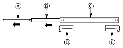
A. Inner Member | Narrowest piece of the assembly. |
B. Intermediate Member | Middle member of the assembly. |
C. Outer Member | Widest piece of the assembly. |
D. Front Left Bracket | Labeled FL/RR. |
E. Rear Left Bracket | Labeled FR/RL. |
The inner member has a safety latch shown in Figure 1-2. Without fully extending the assembly, you can move the server in and out from the rack. When the assembly is fully extended, this latch locks the assembly in the fully extended position. When you depress the latch, you can release the inner member from the rest of the assembly.

A. Inner Member | Narrowest piece of the assembly. Attached to the chassis. |
B. Safety Latch | Located on the inner member. |
C. Intermediate Member | Slides into the inner member. |
| Warning: You must anchor the equipment rack to an unmovable support to prevent it from falling over when the server is pulled on the assembly. The anchors must be able to withstand a force of up to 113 kg (250 lbs). You must also consider the weight of any other device installed in the rack. |
| Caution: After completing the rack mount installation, do not depress the safety latch unless you are removing the chassis from the rack. The purpose of the safety latch is to prevent the server from unexpectedly sliding out of the rack. |
To prepare the slide rail assemblies, follow these steps:
Remove the assemblies from the kit.
Orient the assembly so that the inside of the inner member is facing up and the safety latch is visible.
Fully extend the telescoping assembly until the intermediate member hits the safety latch on the inner member.
Depress the safety latch with your thumb. Pull the inner member away from the intermediate member until the inner member separates from the rest of the assembly.
Set the intermediate and outer members of the assembly aside. You will need them later.
To prepare the server, follow these steps:
Remove six #10-32 x 1/4 long pan-head screws from the kit.
Orient the first inner member so that the latch points towards the rear of the chassis.
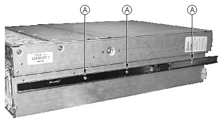
Figure 1-3 shows the inner member attached to the chassis (the inner member is noted by “A”). Notice that the safety latch is pointed towards the rear of the chassis.
Align the three holes in the inner member with the three holes in the chassis.
Insert and tighten a screw through each hole in the bar and chassis wall.
Repeat steps 2 through 4 for the other inner member on the other side of the chassis.
At this point, you have removed the inner member from the slide rail assembly. The outer and intermediate members comprise the assembly. This section explains how to attach the front and rear brackets. Note the location of the brackets in Figure 1-1.
 | Note: Mounting holes in the vertical rails of equipment racks are commonly spaced in a 5/8 x 5/8 x 1/2-inch sequence. Perform the steps in the following sections carefully; brackets must be mounted with precision to allow room for the next server you install in a rack. |
To attach the front bracket to the slide rail assembly, follow these steps:
Remove two #8-32 x 1/2 long pan-head screws, two washers, and two locknuts from the kit.
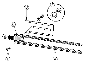
Extend the intermediate member out from the outer member so that the hole at the front end of the outer member is visible through a rectangular hole in the intermediate member. Item B in Figure 1-5 shows the direction in which you must extend the intermediate member.
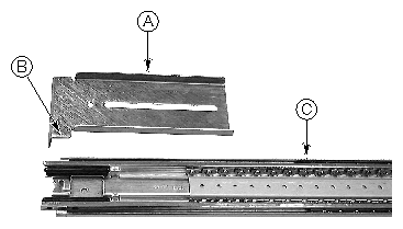
Figure 1-4 shows how the FL/RR bracket is oriented and how the slide rail assembly is extended.
A. Front Left Bracket
The front left bracket is labeled FL/RR.
B. Lower Tongue
The correct orientation of the lower tongue of the bracket safety latch is shown.
C. Extended Slide Rail Assembly
The intermediate member is extended so that the rectangular hole in the screw hole in the outer member is centered in the rectangular hole of the intermediate member.
Place one of the brackets labeled FL/RR on the outside of the outer member. The lower tongue of the bracket must be oriented correctly. Item B in Figure 1-4 shows the bracket's correct orientation.
Place a screw in the holes from inside the intermediate member and tighten with a washer and lock nut. The correct alignment of the screw, washer, locknut, bracket, and slide assembly is shown in Figure 1-5.
A. Extended Slide Rail Assembly
The assembly is extended so that the screw hole in the outer member is centered in the rectangular hole of the intermediate member.
B. Extension Direction
The intermediate member is extended in this direction.
C. Rectangular Hole
The screw hole is centered in the rectangular hole of the intermediate member.
D. Front Left Bracket
The front left bracket is labeled FL/RR.
E. Screw
The screw secures the bracket to the assembly.
F. Washer and Locknut
The correct orientation of the washer and locknut is shown.
Caution: Before continuing, make sure that the screw connecting the front bracket is tightened securely. If it is not, the rack installation may not be able to support the weight of the server. Slide the intermediate member back and forth over the screw you just tightened. If the intermediate member cannot slide over the screw, make sure the screw size is correct.
Repeat steps 2 through 5 for the other assembly.
To attach the rear bracket to the slide rail assembly, follow these steps:
Remove four #8-32 x 1/2 long pan-head screws, four washers, and four locknuts from the kit.
Extend the intermediate member out from the outer member so that you have complete access to the rear part of the outer member. Item B in Figure 1-7 shows the direction in which you must extend the intermediate member. On the right side of the assembly, notice that the three screw holes in the outer member are accessible.
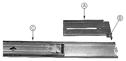
Place one of the brackets labeled FR/RL on the outside of the outer member. The lower tongue of the bracket must be oriented correctly. Item B in Figure 1-6 shows the correct orientation.
Figure 1-6 shows how the FR/RL bracket is oriented and how the slide rail assembly is extended.
A. Rear Left Bracket
The front left bracket is labeled FR/RL.
B. Lower Tongue
The correct orientation of the lower tongue of the bracket safety latch is shown.
C. Extended Slide Rail Assembly
The intermediate member is extended so that the three screw holes on the outer member are accessible.
Align the slot in the bracket with the three holes in the outer member so that all three holes in the outer member are visible through the slot in the bracket.
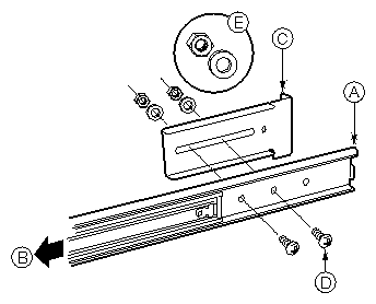
Place screws in the two front holes from inside the outer member and loosely tighten with a washer and lock nut. See Figure 1-7 for an illustration of the alignment of the screw, washer, locknut, bracket, and assembly.
Note: You might need to place the screws in the two rear holes depending on the distance between the front and rear sides of the rack. A. Extended Slide Rail Assembly
The assembly is extended so that there is complete access to the rear part of the outer member.
B. Extension Direction
The intermediate member is extended in this direction.
C. Rear Left Bracket
The rear left bracket is labeled FR/RL.
D. Screw
One of two screws secures the bracket to the assembly.
E. Washer and Locknut
The correct orientation of the washer and locknut for each screw is shown.
Slide the bracket back and forth. Make sure that the screws are loose enough to allow the bracket to move freely.
Repeat steps 2 through 6 for the other assembly.
To attach the assembly to the rack, follow these steps:
Obtain eight screws from your own inventory.
Select the holes you will use on the rack.
Align the holes on one of the front brackets with the holes you selected on the rack.
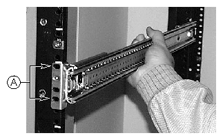
Figure 1-8 shows the slide rail assembly aligned with the holes in the rack. The holes are noted by “A.”
As shown in Figure 1-8, insert two screws in the front bracket and rack holes. Tighten the screws to secure the front of the assembly to the rack.
Adjust the rear bracket so that it meets the rear vertical rail of the rack.
Insert two screws in the rear bracket and rack holes. Tighten the screws to secure the rear of the assembly to the rack.
Tighten the two screws that secure the assembly to the rear bracket.
Repeat steps 2 through 7 for the other slide rail assembly.
Lift the chassis with a hand-truck or other mechanical assist unit so that the inner members on the server align with the slide rail assembly attached to the rack. Gently push the chassis into the rack. Make sure that the inner member slides smoothly into the assembly in the rack.
The SGI 1450 is shipped with a rack mount handle kit. This kit consists of a left handle, a right handle, and four screws. The handles attach to the chassis. As an option, you can also attach them to the rack. To install the handles, follow these steps:
Make sure that you pull the chassis out of the rack until the safety latch snaps into place.
As shown in Figure 1-9, align the inside top and bottom holes of the handles with the top and bottom holes of the chassis.
Place screws in the top and bottom holes on the inside edge of each handle. Tighten each set of screws to secure each handle to the chassis.
If you want to secure the handles to the rack, place screws in the top and bottom holes on the outside edge of each handle. Tighten each set of screws.

The front bezel attaches to and protects the front of the server.
Make sure that you pull the chassis out of the rack until the safety latch snaps into place.
Place the front bezel over the front of the chassis. The edge of the bezel should align with the front edges of the chassis. The ball studs on the back of the bezel fit easily into holes on the front of the server.
Gently push the front bezel into the chassis. The front bezel snaps into place.
To remove the server from the rack, follow these steps:
Pull the server out until the safety latches on each side lock into place.
Make sure that a hand-truck or other mechanical assist unit is placed directly under the server.
Depress the safety latches on both sides and simultaneously pull the chassis out of the slide rail assembly.
Pull out the hand-truck or other mechanical assist unit along with the chassis.
This section provides pedestal mounting instructions. This includes the installation of a pedestal kit, the removal of the side cover for service access, and the conversion of the server from pedestal mode to rack mode.
To convert the server from rack mode to pedestal mode, you must install a pedestal kit. The pedestal kit consists of a sheet metal casing, a side cover, and seven screws. Figure 1-13 shows the SGI 1450 in pedestal mode. To install the pedestal kit, follow these steps:
Place the server upside down on a flat and stable surface. The front and top covers must be facing down (see Figure 1-10).
Caution: The server in its maximum configuration weighs up to 45 kg (100 lbs). Ensure that the surface on which you are installing the pedestal kit is capable of handling the load. Slide the sheet metal casing onto the server, as shown in Figure 1-10. The narrowest side of the casing corresponds to the rear of the chassis.
Attach the screws that secure the sheet metal to the server. There are three screws on the bottom side (the side of the hard drive bay) and four screws on the top side (the side of the power subsystem bay).
Set the server on its side, with the power subsystem bay side on top, as shown in Figure 1-11.
If the front bezel has been removed, install it by placing it over the front of the chassis. The edge of the bezel should align with the front edges of the chassis. Gently push the front bezel into the chassis so as to snap the ball studs into place.
Place the lower side of the side cover on the chassis, so as to insert the cover's bottom latches into their respective slots in the chassis. (See Figure 1-11.)
Gently push the cover toward the server, and insert the three top latches into their respective slots in the server, as shown in Figure 1-11.
Push the side cover toward the rear of the server until it snaps into place, as shown in Figure 1-12.

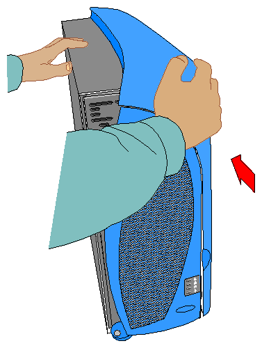
If your SGI 1450 server is in pedestal mode configuration and you need to open the server for service or upgrade, then you need to remove the side cover.
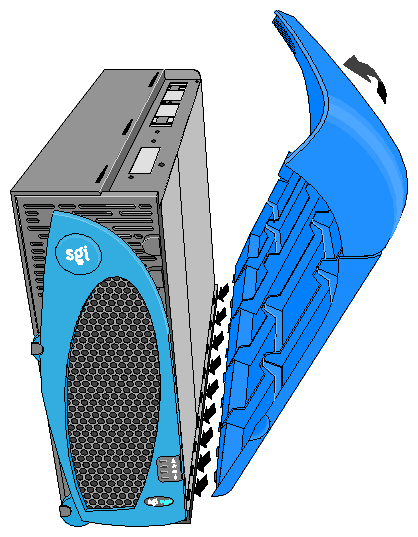
To remove the side cover from the server, follow these steps (see Figure 1-13 for an illustration of the pedestal mode):

While pulling on the rear latch, slide the cover toward the front of the server.
Lift the three top cover latches up and away from the chassis, as shown in Figure 1-14.
Remove the side cover by lifting it up and away from the chassis.

If you want to install the pedestal version of the SGI 1450 server in a 19-inch rack, you need to remove both the side cover and the sheet metal casing. To remove the pedestal kit, follow these steps;
Remove the side cover as described in the previous section, “Removing the Side Cover from the Server in Pedestal Mode”.
Remove the bezel by gently pulling on its edges to release the ball studs.
Place the server upside down on a flat and stable surface. The front and top covers must be facing down (see Figure 1-10).
Caution: The server in its maximum configuration weighs up to 45 kg (100 lbs). Ensure that the surface on which you are installing the pedestal kit is capable of handling the load. Remove the screws that secure the sheet metal to the server. There are three screws on the bottom side (the side of the hard drive bay) and four screws on the top side (the side of the power subsystem bay).
Lift the sheet metal casing away from the server.
Proceed with the rack mounting installation starting with “Checking the Slide Rail Kit”.