This Appendix contains port pinout information for the following ports:
The SGI 1100 server uses a standard PS/2 keyboard port.
Figure C-1 shows the PS/2 keyboard port.
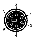
Table C-1 shows the cable pinout assignments for the keyboard port.
Table C-1. Keyboard Port Pinout
Pin | Assignment |
|---|---|
1 | Keyboard Data |
2 | (Reserved) |
3 | Ground |
4 | Keyboard Power (+5V) |
5 | Keyboard Clock |
6 | (Reserved) |
The SGI 1100 server uses a standard PS/2 mouse port.
Figure C-2 shows the PS/2 mouse port.
Table C-2 shows the cable pinout assignments for the mouse port.
The SGI 1100 server comes with a DB15 HD video port.
Figure C-3 shows the DB15 HD video port.
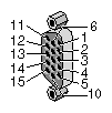
Table C-3 shows the cable pinout assignments for the DB15 HD video port.
Table C-3. DB15 HD Port Pinout
Pin | Assignment | Pin | Assignment |
|---|---|---|---|
1 | Red | 9 | No Connect |
2 | Green | 10 | Ground |
3 | Blue | 11 | Ground |
4 | Ground | 12 | IIC Data |
5 | Ground | 13 | Horizontal Sync |
6 | Red Return | 14 | Vertical Sync |
7 | Green Return | 15 | IIC Clock |
8 | Blue Return |
|
|
The SGI 1100 server has two PC-compatible serial ports. The serial port supports data rates from 300 bits per second (bps) to 115.2 Kbps.
Figure C-4 shows the serial port.
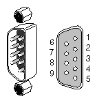
Table C-4 shows cable pinout assignments for the serial ports.
Pin | Assignment | Description |
|---|---|---|
1 | DCD | Data Carrier Detect |
2 | RD | Receive Data |
3 | TD | Transmit Data |
4 | DTR | Data Terminal Ready |
5 | SG | Signal Ground |
6 | DSR | Data Set Ready |
7 | RTS | Request to Send |
8 | CTS | Clear to Send |
9 | RI | Ring Indicator |
The SGI 1100 server has two 4-pin USB ports.
Figure C-5 shows the USB port.
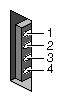
Table C-5 shows the cable pinout assignments for the USB ports.
Pin | Assignment | Color | Comment |
|---|---|---|---|
1 | VCC | Red | Cable power |
2 | -Data | White |
|
3 | +Data | Green |
|
4 | Ground | Black | Cable ground |
The SGI 1100 server has two RJ45 ports for 10-Base-T or 100-Base-TX twisted-pair Ethernet. The ports autoselect the speed (10 Mbps or 100 Mbps) and type (half duplex or full duplex) at bootup, based on what they are connected to.
Figure C-6 shows the Ethernet port.
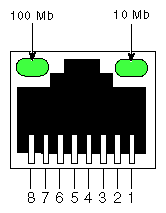
Table C-6 shows the cable pinout assignments for the Ethernet port.
Table C-6. Ethernet Port Pinout
Pin | Assignment |
|---|---|
1 | Transmit+ |
2 | Transmit– |
3 | Receive+ |
4 | (Reserved) |
5 | (Reserved) |
6 | Receive– |
7 | (Reserved) |
8 | (Reserved) |