Use this document to help diagnose problems, replace components, or upgrade the system.
The following visual indicators on the SGI 1200 server help diagnose some problems .
For a non-responsive system, check the LEDs on the back of the power supply. If the green LED is dark and the amber LED is lit, then the power supply voltages may not be within range or the power supply may have failed.
If the amber Global Failure LED on the front panel lights solidly , one of the following conditions has occurred:
If the amber LED global failure on the front panel flashes very slowly (once every 50 to 80 seconds), one of the following conditions has occurred:
Optional RAID array in critical, degraded state requiring immediate attention
Optional RAID array in degraded state, but rebuilding data on a new drive
If the amber Global Failure LED blinks very slowly and a red LED on an individual removable hard drive lights continuously, the RAID controller has found a failed hard drive. With a ready spare hard drive, remove the hard drive carrier, and replace it. See ???.
Table 1-1. RAID Hot-swap Hard Drive Status (Midplane Only)
Hot-swap Drive Status | ||
|---|---|---|
Normal operation | Off | Off |
Drive failure | On (lit) | On (lit) |
RAID drive being rebuilt | Very slow (50 to 80 second) blinking | |
RAID drive offline | Off | Off |
Many of the procedures in this section can be completed without the use of tools.
 | Warning: The procedures in this section are intended for authorized service personnel only. The front power button does not turn off the system AC power. You must unplug the AC power cord before opening the top cover. |
 | Caution: The components within the chassis are extremely sensitive to Electrostatic Discharge (ESD). Be sure to use all possible ESD protective procedures. At minimum, wear an antistatic wrist strap attached to the chassis ground (an unpainted surface). |
Prepare the chassis for maintenance:
Log all users off the system.
Shut down the operating system.
Unplug the AC power cord from the chassis.
Slip on a wrist strap that is attached to chassis ground.
The SGI 1200 server has a two section top cover. As viewed from the front, the front section of the top cover that houses the disk drives is not removable. The back section of the top cover attaches to the chassis with a sheet metal lip and two screws . You can use a coin or a flat-bladed screwdriver to loosen these screws. To remove the cover:
Face the back of the chassis.
Use a flat-bladed screwdriver or a coin to turn each of the screws counterclockwise.
When the thread is disengaged, the fastener retracts fully, but remains attached to the lid.
Once the screws are released, a lip on the edge of the cover keeps the cover in place.
Grasp each side of the cover and slide it toward you.
The lid has a lip to grip the lid.
Remove the top cover.
The motherboard can be upgraded from the base configuration of 128 MB of memory to 2 GB of memory with registered 100 MHz Error Correcting Code (ECC ) Synchronous Dynamic Random Access Memory (SDRAM) Dual-Inline Memory Module (DIMM)s from approved memory vendors.
 | Note: Contact your sales representative or service provider for information on approved memory upgrades for your server. |
| Caution: All memory on the motherboard must be from the same vendor. All memory must be registered ECC memory. Unbuffered and registered ECC memory cannot be mixed. Use of unauthorized memory can result in intermittent failures. Motherboards using unauthorized memory are not supported. |
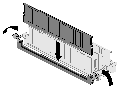
See Figure 1-1 for the location and numbering of the DIMMs. Use these steps to properly install additional DIMMs:
Remove the DIMM from its packaging.
Align the two edges at the bottom of the DIMM with the keyed socket. See Figure 1-1.
Press the bottom edge of the DIMM down into the socket.
Lock each end of the DIMM with the plastic ejector lever once the DIMM is firmly seated in the connector.
Repeat this procedure for each DIMM.
The fans are installed into the chassis with a friction fit. No tools are needed to remove them.
To remove a fan:
Open the chassis cover.
Locate the failed fan.
Disconnect the DC power cord from its header on the midplane. Note the location of the DC header for re-installation.
Pull the fan up.
Orient the fan so that it blows air from the midplane toward the back of the chassis.
Push the fan down firmly into the metal fan holder until it snaps into place.
Connect the DC power cord to its header on the motherboard.
Close the chassis cover.
The power supply attaches to the chassis with two metal tabs on the bottom of the power supply. It can be removed without using tools. To remove the power supply:
Face the back of the chassis.
Remove the AC power cord.
Remove the top cover.
Using your thumbs, push the metal grill of the power supply toward the fans. Move it about a half an inch (12.7 cm), until it disengages from the tabs that hold it to the chassis.
Slide the power supply away from the chassis wall toward the motherboard.
Grasp the AC power receptacle with one hand and the power supply canister with the other hand and lift the power supply up and away from the chassis.
Disconnect the power supply harness.
Remove the power supply.
Reverse the steps above to install a new power supply.
Use the following information to replace the power distribution board:
Open top cover as described in “Opening the Top Cover ”.
Remove the power supply fan's power connector cable. This connector is located at the front of the power supply, on the interior of the chassis, directly next to the power supply's interior fan. Using your thumb and forefinger, squeeze the retaining clip on the power connector to disengage the safety clip, then pull to disengage the connector from the power supply.
Next, disconnect the power distribution board from the power supply. This board connects to the front of the power supply with a clipless connector. Removal requires sliding the entire power distribution board toward the front of the chassis.
The power distribution board now has two remaining wiresets leading to two remaining connectors; one supplies power to the motherboard and one supplies power to the SCA SCSI midplane.
Note: Both of the power connectors are held in place by small retention clips. Disengage these retention clips by squeezing them gently with your thumb and forefinger. When both of these connectors have been disengaged, the power distribution board can be safely removed from the chassis.
Replace the power distribution board by reversing steps 1 through 4, above.
Use the following steps to replace or add a CPU to the server:
Remove the chassis top cover as described in “Opening the Top Cover ”.
Remove all the system memory DIMMs as described in “Upgrading Memory ”.
Start the CPU removal process by unplugging the processor's heatsink fan power connector. This is a small wireset leading from the CPU fan to the motherboard.
To remove each CPU, gently pull one side of the CPU retention mechanism (mounting bracket) away from the CPU. After the retaining latch has cleared the CPU, one side of the CPU may be lifted slightly to unseat the CPU. Repeat this step to the opposite side of the CPU to completely unlock the CPU from its retaining brackets, then slide the CPU out of the motherboard and place it in an electrostatically-neutral protective bag.
Install the new CPU by aligning the CPU into the retention mechanism and sliding it downward and into the chassis until the retaining brackets lock it into place.
Use the following steps to replace the server's motherboard:
Remove the chassis top cover as described in “Opening the Top Cover ”.
Remove all system memory DIMMs as described in “Upgrading Memory ”.
Remove system CPU(s) as described in “Replacing or Adding CPUs”.
Remove all internal PCI cards using the information in the section “Adding Optional PCI Cards”.
Unplug the power cable from the motherboard by squeezing it to disengage the retaining clip and pulling it away from the motherboard.
If SCSI cables are present, note the location of each connector and to which motherboard connector each cable is attached to. Label them if necessary, and unplug them from the motherboard.
If an IDE cable is present, unplug it from the motherboard.
Unplug the Floppy cable from the motherboard.
Unplug the Front Panel Connector cable from the motherboard.
Using a Phillips screwdriver, remove all the screws holding the motherboard to the floor of the chassis, (twelve screws total) and set them aside.
The motherboard may now be safely removed by pushing it toward the front of the chassis until it's rear external connector group has cleared the metal chassis dust gasket and then lifting it from the case.
Place the motherboard in an electrostatically-neutral bag.
Unpack the new motherboard and attach the CPU retention brackets.
Install the new motherboard by reversing steps 1 through 11, above.
Use the following steps to replace the battery on the system motherboard.
Open the chassis top cover, as detailed in “Opening the Top Cover ”.
Insert the tip of a small flat-bladed screwdriver or equivalent under the tab of the plastic battery retainer.
Use the screwdriver to gently pry the battery from the socket and remove.
Place the new lithium battery into the battery socket, being careful to observe the correct polarity of the battery. (Battery should be inserted with its positive terminal facing upward).
Close the chassis and run the System Setup Utility on the motherboard CD to restore the Real Time Clock configuration settings.
To replace the SCA SCSI midplane use the following steps:
Remove the chassis top cover as described in “Opening the Top Cover ”“Opening the Top Cover ”.
Remove the Power Distribution Board, as described in “Power Distribution Board Replacement”.
Remove the Floppy/CD-ROM carrier as described in “Removing the CD and Floppy drive Assembly ”.
Keeping in mind optional RAID considerations, mark the locations of all SCA drives and remove all SCA drives as described in “Hard Drive Carrier Removal and Replacement”.
Disconnect the SCSI ribbon cable from the SCA backplane.
Remove all internal fans as described in “SCA Midplane Replacement”.
Disconnect the Front Panel ribbon cable from the SCA backplane. (This is a small ribbon cable located just forward of the primary and secondary IDE connectors on the motherboard). Its connector is marked on the motherboard with the word FRONT PANEL nearby. You may leave the motherboard end of this cable connected.
Using a Phillips screwdriver, remove the three screws holding the midplane fan assembly onto the chassis. (The fan assembly held two internal fans and is secured to the chassis by three screws, two that are threaded through the midplane itself and one that secures the assembly to the floor of the chassis.) Lay these screws aside in a safe place.
Remove the fan assembly from the chassis.
Remove the three remaining screws securing the SCA backplane to the chassis.
Rock the top of the midplane back, into the chassis.
Disconnect the front panel LED/Switch ribbon cable from the midplane. This cable is not accessible until the midplane has been partially dislodged (see Step 11, above).
Continue to pivot the top of the midplane downward and inward until the midplane is horizontal to the floor of the chassis and the internal SCA drive connectors face upward. Remove the midplane by first tipping one end upward until it clears the outer edge of the chassis opening, then pull the entire card up and out of the chassis.
Reverse Steps 1 through 13 above to install a new SCA SCSI midplane.
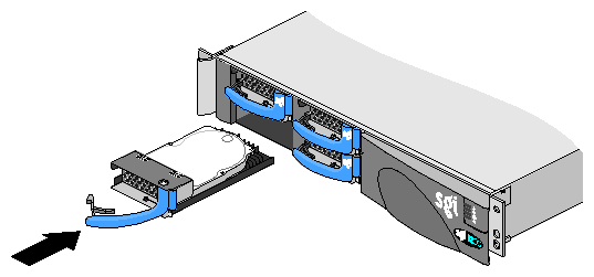
Hard drives slide into the SGI 1200 server midplane as shown in Figure 1-2. The SGI 1200 server can be configured with up to four hard disk drives. Note that the drives are only hot-swappable when using a PCI RAID option.
To add or replace a new hard drive:
Gracefully shut down the system (not required with PCI RAID option).
Remove the hard drive blank (or malfunctioning drive) from the drive bay.
Slide the new disk into the hard drive bay as shown in Figure 1-2.
Note: SCSI IDs are set by the midplane and the SCA hard drive. No jumpers need to be set.
See the SGI 1200-Family of Servers User's Guide for more information about hard drive replacement strategies for RAID and non-RAID systems.
Follow the procedure below to remove the CD and floppy drive assembly:
Remove the front drive cover.
Open the top cover.
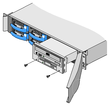
Remove the floppy/ CD-ROM carrier . The floppy/CD-ROM carrier is attached to the chassis by two screws on the front panel. Remove these two front panel screws (see Figure 1-3) with a #2 Phillips screwdriver.
Push the floppy/CD-ROM carrier halfway out of the front of the chassis.
Reach around to the back of the floppy/CD-ROM carrier. While being careful not to detach the CD-ROM or floppy cables, push the frame of the floppy/CD-ROM carrier out of front of the chassis.
The SGI 1200 server chassis allows the addition of one or two full or half-sized PCI cards that adhere to the physical dimensions of Intel's PCI Specification 2.2. Full size or half size PCI cards can be installed into either of the two PCI slots. Follow these steps to install optional PCI cards.
| Caution: Electrostatic discharge (ESD) can damage PCI cards and other components. Be sure to use all possible ESD protective procedures. At a minimum, you must wear an antistatic wrist strap attached to chassis ground (an unpainted metal surface on the server chassis). |
Remove the locking tab next to the power supply.
Slide the PCI board along the white plastic tab and press the card edge connector into the PCI riser.
Attach any cables.
With the long leg of the locking tab oriented toward the power supply location, press the locking tab down firmly until it snaps into place. See Figure 1-4.
Close the chassis, plug in the AC power chord, set the latency timer for the PCI device in the BIOS (as applicable) and boot the operating system.
