This appendix provides information to help you remove the ioconfig.conf file, and connect cables to the correct port on a particular PCI board. Configuration resources are provided in the last section of this appendix.
The ioconfig.conf file records and saves option board and port information after the option board is installed in the OCTANE workstation. However, the file reserves the board and port spaces if the option board is removed, and assigns new logical controller numbers if the same type of board is inserted in a different PCI slot.
However, if you wish to have a listing of only what is currently installed, remove the ioconfig.conf file and restart your system. The file is rebuilt with information about the current hardware configuration reflecting what is currently installed.
 | Note: Rebuilding the ioconfig.conf file can change all of the maps between the logical controller numbers and the physical port locations, depending on whether option boards have been moved to different slots or removed from the system. |
If you need to place the PCI board (Ethernet/keyboard/mouse) in a different slot, move the board to the new slot, and then remove the ioconfig.conf file. Removing the file erases the memory of the previous location so that the system does not think two boards of the same type are installed. To remove the iconfig.conf file, follow these directions:
From the Toolchest > Desktop, open a UNIX shell.
Become superuser.
Type: rm /etc/ioconfig.conf
Type: exit to exit superuser mode.
Restart the system. Restarting the system builds a new ioconfig.conf file.
Before you can connect cables, you need to map the logical ports numbers to the physical port locations. Follow these instructions:
From the Toolchest > Desktop, open a UNIX shell.
At the prompt, type: cat /etc/ioconfig.conf
Read the following table, descriptions, and explanations to determine the correct port location(s) for the cables you wish to connect.
You see a listing similar to the following example.
Table D-1. Identification of Information in the ioconfig.conf File
Logical
Controller NumberHard
wareNode
Bus Type
Physical XIO Slot ID
Bus Type
Slot ID
Port Type (Abbreviation)
Serial Port ID
2
/hw
/node
/xtalk
/13
/pci
/2
/scsi_ctlr
0
/hw
/node
/xtalk
/13
/pci
/1
/rns
2
/hw
/node
/xtalk
/13
/pci
/3
/pckb
2
/hw
/node
/xtalk
/13
/pci
/3
/pcms
1
/hw
/node
/xtalk
/13
/pci
/3
/ef
The Logical Controller Number is the number assigned to a port on an option board by the operating system. The logical controller numbers assigned by the operating system to a port on an option board always start higher than the last assigned port of the same type on the system module. Ports of the same type are assigned incrementing port numbers. For example, because there is one Ethernet port on the System module, the logical number 1 is assigned to the first optional Ethernet port that the software sees. (The Ethernet port on the system module is assigned logical number 0.)
Ignore the Hardware, Node, and Bus Type columns containing XIO entries when looking for information in this table. They appear in the ioconfig.conf file to report that hardware is being probed, on one node, using XIO at one point and PCI at another within the workstation.
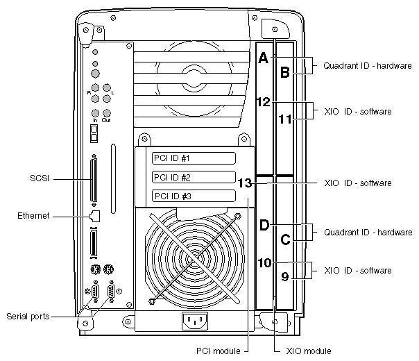
Use Figure D-1 to determine the physical XIO ID number. The PCI module is the first XIO module probed. Its number is 13.
| Note: Physical port numbers are assigned in descending XIO probing order. Example: a port on an Ethernet board in the PCI module (13) will be assigned logical number 1, before an Ethernet port in quadrant C (9) of the XIO module is assigned a logical number, because XIO ID 13 is probed before XIO ID 9. |
The column that contains PCI entries should be read only in conjunction with the Physical XIO Slot ID column that comes before it. If the Physical ID number is 13, the board, to which a logical controller number has been assigned, is in the PCI module.
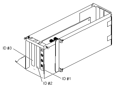
The Slot ID column refers to the physical location of the option board in the PCI module.
Logical | Hard | Node | Bus type | Physical XIO Slot ID | Bus type | Slot ID | Port type (abbreviation) | Serial port ID |
|---|---|---|---|---|---|---|---|---|
2 | /hw | /node | /xtalk | /13 | /pci | /2 | /scsi_ctlr |
|
0 | /hw | /node | /xtalk | /13 | /pci | /1 | /rns |
|
2 | /hw | /node | /xtalk | /13 | /pci | /3 | /pckb |
|
2 | /hw | /node | /xtalk | /13 | /pci | /3 | /pcms |
|
1 | /hw | /node | /xtalk | /13 | /pci | /3 | /ef |
|
The above example shows a PCI module with three boards installed. One of the boards has three ports: a keyboard port, a mouse port, and an Ethernet port. The physical XIO identification number is 13, meaning these are PCI boards. The slot identification number matches the PCI slot identification number in the PCI module. The board with three ports is in slot 3. Slot 1 contains an FDDI or CDDI board with one port. Slot 2 contains a board with a SCSI port.
Because each pair of XIO serial ports share a bus, this column identifies which XIO serial port is on which bus.
When the board is installed and connected, and the OCTANE workstation is powered on, use the following information for configuration.
Certain PCI boards require some configuration, others do not. Use the table below to determine whether you need to configure the board.
Table D-3. Determining Which Board to Configure
Configuration Needed | No Configuration Needed |
|---|---|
All networking boards | Mouse, keyboard, SCSI, Radical |
Refer to the Personal System Administration Guide or IRIX Admin: Networking and Mail guides for instructions on configuring software. Both documents are online and accessible from the Toolchest > Help > Online Books. The Personal System Administration Guide is under SGI End User, and the IRIX system administration guides are under SGI Admin.