This chapter describes how to convert an Origin 2000, Onyx2, or SGI 2000 series system to a rackmount configuration. It contains the following sections:
The Origin 2000, Onyx2, and SGI 2000 Series Rackmount Kit provides quick and easy rackmount installation for Origin 2000, Onyx2, or SGI 2000 series systems. It contains all the hardware needed to install one deskside system in a half-size or full-size EIA standard 19-inch equipment rack.
 | Note: This kit is designed for installing SGI systems in single equipment racks only. It is not designed for connecting systems in multiple equipment racks. Any alterations made to the rackmount kit hardware will void the product's warranty. SGI is not responsible for any equipment damage due to alterations in the rackmount hardware. |
Due to the various design configurations of third-party EIA standard 19-inch equipment racks, this rackmount kit does not fit every 19-inch third-party rack. When using a third-party rack, it is acceptable to use the support shelves provided by the rack manufacturer if they provide adequate air flow and are designed to support the maximum weight of an SGI system (190 pounds).
Before beginning the installation procedure, verify that all parts necessary for installation are present (see Figure 1-1). If any items are missing, contact SGI or your local service provider. The Rackmount Kit should contain all the following parts:
Intake plenum* (1)
Exhaust plenum (1)
Adjustable shelves (4)
Extender shelves (4)
Chassis brackets (2)
Plenum brackets* (2)
Rear brackets (4)
Shelf brackets* (4)
Plenum front cover* (1)
Front panel (1 - Onyx2, Origin 2000, or SGI 2000 series)
Front panel screws (8)
10-32 x 3/8 flathead mounting screws (22)
8-32 x 3/8 panhead mounting screws (8)
10-32 x 3/8 panhead mounting screws (80)
10-32 kep nuts (80)
Flat washers (72)
* Optional equipment. Shelf brackets are required only for systems without side mounting retma rails. The top intake plenum is not required with an SGI system that is mounted in the top of a rack and if the top of the rack meets the following conditions:

The Origin 2000, Onyx2, and SGI 2000 series products have been certified and licensed by international safety agencies for use in the following ways:
As stand-alone units
For installation in SGI model CMN-A017 rack systems
Although the hardware in this kit enables you to mount these systems in third-party EIA standard 19-inch equipment racks, installation in such racks may require submittal to an approved safety agency for their evaluation and certification/licensing of the new rack-system combination. Check with your local building inspector for requirements applicable to your location.
This kit is not designed for shock and vibration dampening. If operating an SGI system in a harsh environment subject to intense vibration, it is recommended that you configure the rack with appropriate mounting hardware to protect the integrity of the system components.
To prepare the Origin 2000, Onyx2, or SGI 2000 series system for installation, see Figures 1-2 through 1-5 and complete the following procedures.
Shut down the system.
Disconnect all cables at the rear of the system, including the cables for power, networking, serial, router interconnect, grounding, and so on.
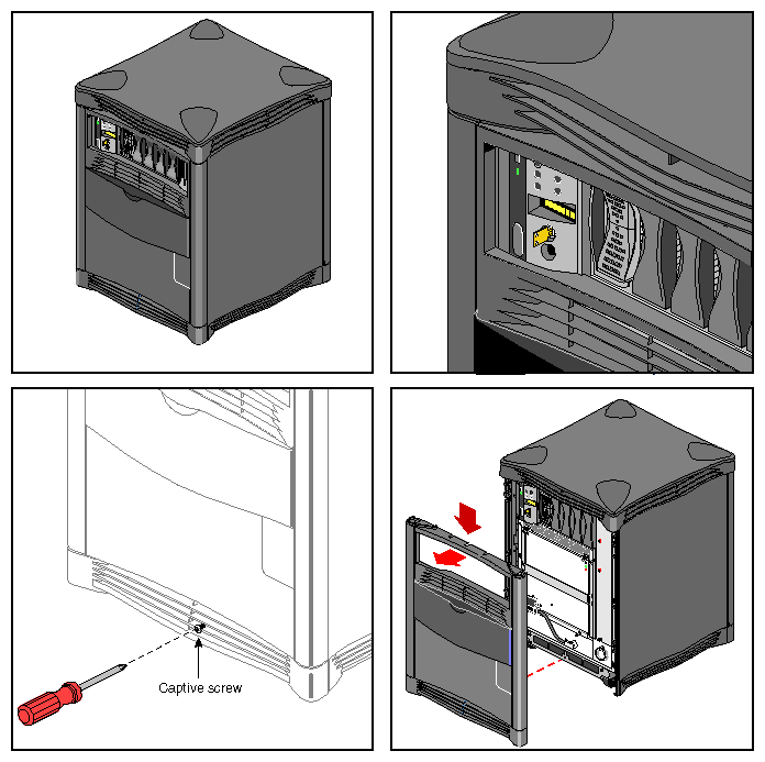
To remove the system facade (or front door), see Figure 1-2 and follow these steps:
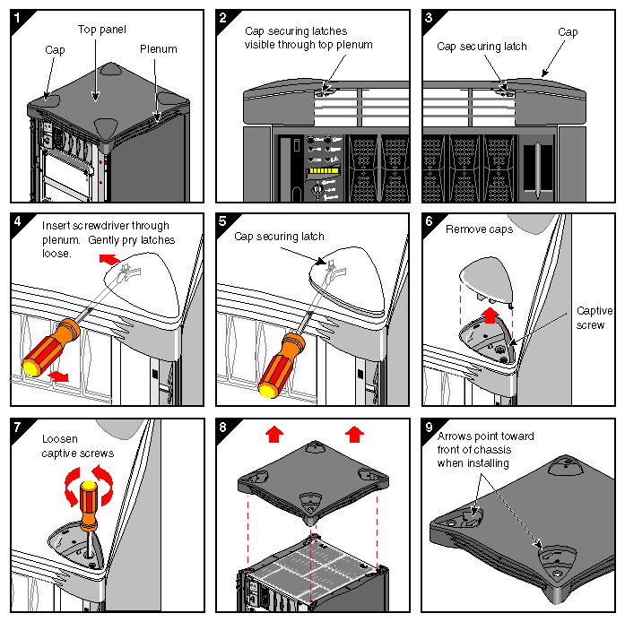
To remove the system tophat, see Figure 1-3 and follow these steps:
Remove the system tophat by inserting a flathead screwdriver under one of the four tophat caps (panel 4).
Locate the securing latch towards the rear of the cap and push the latch forward (panel 5).
Lift up the cap (panel 6).
Repeat steps 1 through 3 for each of the caps.
Remove the four screws that hold the tophat to the system chassis (panel 7).
Remove the tophat (panel 8).
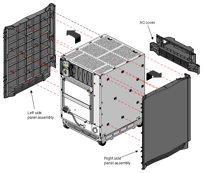
To remove the system side panels, see Figure 1-4 and follow these steps:
To remove the system bottom plenum and pedestal assembly, see Figure 1-5 and follow these steps:

To install a system chassis in an EIA standard 19-inch equipment rack and attach the Rackmount Kit hardware, see Figures 1-6 through 1-9 and follow these steps:
Select a location within the equipment rack where the system will be located. The system requires 18 rack units (U) with the intake plenum and 15U without the intake plenum. (One rack unit is equal to 1.75 inches.)
Connect the adjustable shelf to the extender shelf with the mounting screws (see Figure 1-6). You can adjust this hardware to accommodate various depths. The final shelf assembly length should be able to mount between the front and rear retma rails. (You can also use the shelving hardware supplied with the rack, if applicable.)
Note: Some equipment racks do not have the side retma rails required for side mounting the shelf assemblies as shown in Figure 1-6. In such cases, you must use the shelf brackets to mount the shelf assemblies to the front and rear retma rails, as shown in Figure 1-7. If both types of retma rails are available, side mounting is recommended. Attach the left and right exhaust plenum shelf assemblies to the equipment rack front and rear retma rails with the mounting screws (see Figure 1-6 or Figure 1-7). The adjustable shelves should be facing toward the front of the rack. (This shelf assembly supports the bottom of the exhaust plenum. Be sure to position the shelf assembly in the exact area where the exhaust plenum will be located.)
Attach the left and right system chassis shelf assemblies to the equipment rack with the mounting screws (see Figure 1-6 or Figure 1-7). The adjustable shelves should be facing toward the front of the rack. (This shelf assembly supports the bottom of the system chassis and must be positioned 3U above the exhaust plenum shelf assembly.)
Position the exhaust plenum on the lower shelf assemblies and slide the plenum three-fourths of the way into the equipment rack (see Figure 1-8). Be sure the open side of the plenum is facing up and the open end is facing the rear.
Note: To ensure proper installation, remove the rectangular bracket from the plenum before sliding it into the equipment rack. Discard the bracket after installation. Position the system chassis on top of the upper shelf assemblies and slide the system three-fourths of the way into the equipment rack (see Figure 1-8).
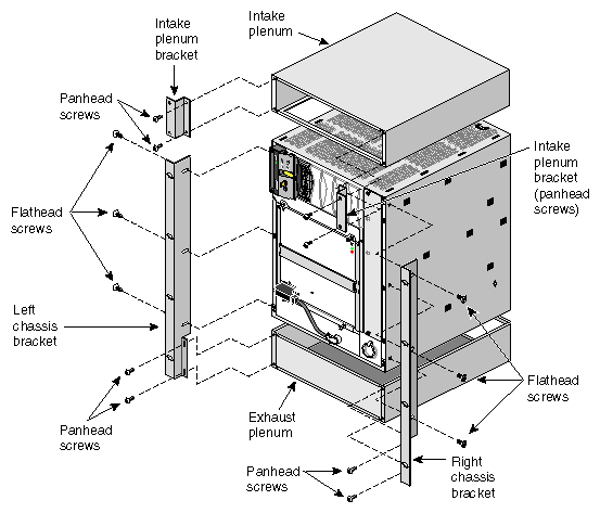
Loosely attach the left and right chassis brackets to the system chassis and the exhaust plenum with the flathead and panhead mounting screws (see Figure 1-8).
Slide the system chassis and the exhaust plenum completely into the system until the chassis brackets rest against the retma rails.
An intake plenum is required to ensure proper air flow when installing an SGI system in the bottom of an equipment rack or the top of an equipment rack with a covered top. If needed, position the intake plenum on top of the system chassis and attach the plenum brackets to the plenum with the mounting screws (see Figure 1-8). Be sure the open side of the plenum is facing down and the open end is facing the front.
Note: To ensure proper installation, remove the rectangular bracket from the plenum before sliding it into the equipment rack. Discard the bracket after installation. Position the front panel mounting holes over the chassis bracket mounting holes and attach the panel and chassis brackets to the equipment rack front retma rails with the mounting screws (see Figure 1-9).
Note: If an intake plenum is installed, attach the front plenum cover in the same manner as the front panel.
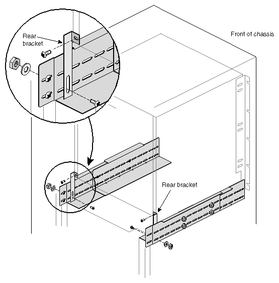
To ensure system stabilization, use the mounting screws to attach one end of the rear brackets to the lower, rear left side and right side of the system chassis (see Figure 1-10). Then attach the other end of the rear brackets to the left and right rear chassis shelf assemblies.
To ensure exhaust plenum stabilization, use the mounting screws to attach one end of the rear brackets to the rear left and right side of the exhaust plenum. Then attach the other end of the rear brackets to the left and right rear exhaust plenum shelf assemblies.
The system chassis rackmount installation is now complete. Connect all cables at the rear of the system, including the cables for power, networking, serial, router interconnect, and grounding. Then power on the system.