This chapter describes how to convert an Origin200 server or Origin Vault expansion cabinet from a tower configuration to a rackmount configuration. It contains the following sections:
“Checking the Kit Contents” lists the contents of this rackmount kit.
“Preparing the System” describes how to prepare the system for installing the kit.
“Removing Components” describes what components you must remove from the system.
“Attaching the Rackmount Hardware” shows how to attach the rackmounting ears to the sides of the chassis.
“Installing the System In a Rack” describes how to install the rackmounting rails and the system in an equipment rack.
The rackmount kit ships with the items shown in Figure 1-1 and Table 1-1. If any of these items are missing, contact Silicon Graphics or your local service provider.

Table 1-1. Contents of the Rackmount Upgrade Kit
Item | Quantity | Silicon Graphics Part Number |
|---|---|---|
Mounting shelf | 1 | 040-2083-001 |
Mounting ears | 1 | 040-2006-001 (right) |
Door assist tab | 1 | 040-2005-001 |
End-caps kit, containing 2 caps for 19-inch racks and 2 caps for 21-inch racks. | 1 | 026-1198-001 |
Screws, Phillips head, 6-32 x 1/4-inch | 5 | 7270805 |
Screws, Phillips head, 10-32 x 1/2-inch | 8 | 7260230 |
Washers, #10 (.203 ID x .562 OD x .040 inch thick) | 4 | 7280044 |
Follow these steps to prepare your Origin200 or Origin Vault before installing the rackmount kit:
Shut down the system.
If you are installing the kit on an Origin Vault expansion cabinet, you must first shut down the computer to which it is attached.
Disconnect all cables at the rear of the system, including power, networking, serial, CrayLink™ interconnect, grounding, and so forth.
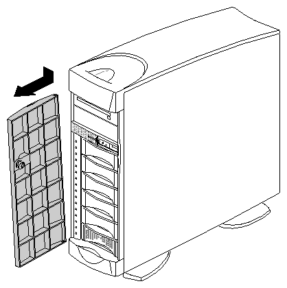
Remove the front door. See Figure 1-2.
Remove all internal 3.5-inch drives.
Be sure to label or otherwise mark the drives so that you can put them back into the correct drive bays. The drives must be replaced in the same drive bays from which you removed them.
If there are any drives in the 5.25-inch peripheral carrier, remove the carrier.
You are now ready to remove external components.
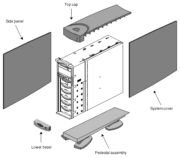
Before installing the rackmount kit, remove the external components shown in Figure 1-3.
Follow these steps to remove the components:
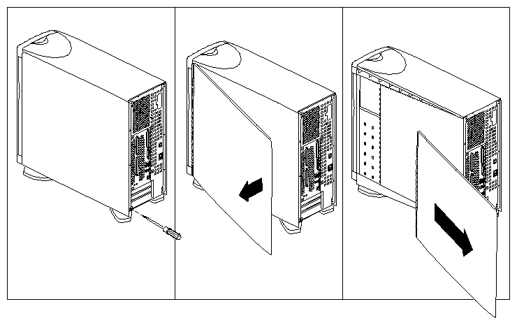
Remove the system cover, as shown in Figure 1-4.
Remove the side panel.
The side panel (shown in Figure 1-3) is identical to the system cover, except that it is on the opposite side of the system. Remove it in the same way.
Remove the top cap, as shown in Figure 1-5.
Insert a flat-blade screwdriver between the top cap and sheet metal, as shown in Figure 1-5.
Twist the screwdriver while pulling the top cap forward. The top cap should move forward slightly as one side disengages from the sheet metal.
Repeat this step on the opposite side of the top cap, as shown in Figure 1-5.
When the second side of the top cap disengages from the sheet metal, pull the top cap forward, then lift it up and off of the chassis.
Remove the lower bezel.
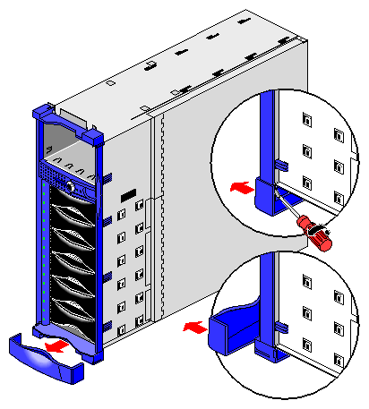
Insert a flat-blade screwdriver between one side of the lower bezel and the sheet metal, as shown in Figure 1-6.
Twist the screwdriver to disengage the lower bezel from the sheet metal.
Pull off the lower bezel.
Remove the pedestal assembly, as shown in Figure 1-7.
Place the system on its side on a sturdy work surface capable of supporting at least 40 pounds (18 kg) and up to 75 pounds (34 kg). Be careful not to scratch or damage the front bezel.
Using a #2 Phillips screwdriver, remove the four screws that hold the pedestal assembly to the chassis and remove the pedestal assembly.


You are finished removing components. You are now ready to install the rackmount kit.
Follow these steps to attach the hardware required to rackmount the chassis:
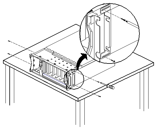
Attach the mounting ears, as shown in Figure 1-8.
Using a #2 Phillips screwdriver and four of the 6-32 x 1/4-inch screws provided with this kit, attach the two rackmounting ears to the sides of the chassis. The ears conform to the shape of the sides of the chassis, and can be installed only one way.
Notice the slots in the sides of the mounting ears that allow you to move the ears forward or backward to adjust how far the chassis extends from the equipment rack.
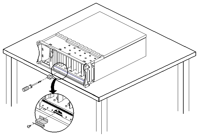
Install the door assist tab using one of the 6-32 x 1/4-inch screws.
The spring-tab provides extra support for the door in a rackmount configuration. If you ever return the system to a tower configuration, be sure to remove this tab as it will interfere with the operation of the door in an upright (tower) system.
Insert the tab between the space in the front bezel and align the tab over the mounting hole, as shown in Figure 1-9.
Using a #2 Phillips screwdriver, secure the door assist tab with a 6-32 x 1/4-inch screw.
You are now ready to install the system in an equipment rack.
Follow these steps to install the Origin200 server or Origin Vault expansion cabinet in an equipment rack.
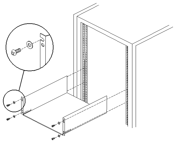
Install the mounting shelf in the equipment rack using four 10-32 x 1/2-inch screws and the four washers, as shown in Figure 1-10.
The mounting shelf uses 4 U (7 inches, or 17.8 cm) of vertical space.
Note that the shelf may not be suitable for use in environments with excessive vibration. See “Mounting and Safety Considerations” for more details. If you use a different mounting system, make sure it can support at least 75 pounds (34 kg).
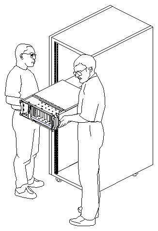
Using two people, one standing on each side of the chassis, lift the system and move it to the side of the equipment rack, as shown in Figure 1-11.
Slide the chassis back into the rack until the mounting ears are flush against the front mounting rails of the rack.
If necessary, you can loosen the mounting ears and slide them forward or backward to adjust how far the chassis extends from the front of the rack.
Fasten the chassis to the front mounting rails with the remaining four
6-32 x 1/4-inch screws.Install one pair of new end caps.
There are two sets of end caps provided. (See Figure 1-1.)
Use the narrower set with 19-inch equipment racks.
Use the larger set with 21-inch equipment racks.
Replace the 5.25-inch peripheral carrier.
Replace any 3.5-inch drives you removed.
Replace the front door, as shown in Figure 1-12.
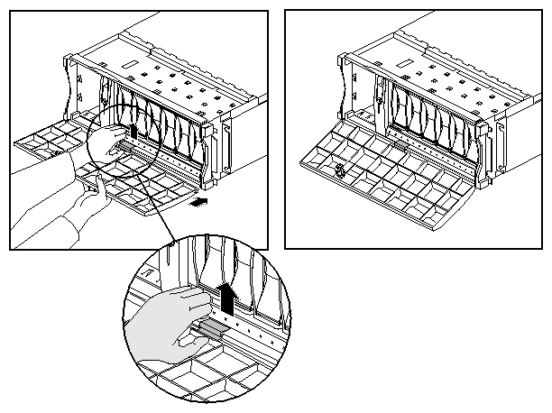
 | Note: If you need to remove the front door in the future (for example, to remove the 5.25-inch peripheral carrier), you must lift up the door assist tab while opening the door. |
You are finished installing the rackmount kit and placing the system in an equipment rack. You may now reattach the various cables and reinstall any 5.25-inch and 3.5-inch drives you removed.
 | Warning: Before connecting two Origin200 modules, always attach the grounding cable between the two modules. If you do not use this grounding cable, differences in ground potential between the two modules may damage internal components. This grounding cable is provided with all two-module Origin200 servers. See your owner's guide for an explanation of the grounding cable and how to install it. |