This chapter provides you with troubleshooting information and one diagnostic test. See Table 5-1 for information about specific symptoms and remedies.
Be sure you have installed any software that came with the second graphics board.
Check the Troubleshooting chapter in your OCTANE Workstation Owner's Guide for troubleshooting tips for the OCTANE workstation.
If the board attached to the primary monitor is removed, the secondary board and monitor by default becomes the primary head.
If you see: | Take this action: | Then: | Then: |
|---|---|---|---|
Blank screen or screen with faulty images: SI/SI or SI with texture memory board/SI configuration. | 1. Using the gfxinfo 2. Read the info
| If both graphics boards
appear in the
inventory, call your If only one board appears in the inventory, perform the diagnostic test in this chapter. | Call your service |
Blank screen or screen with faulty images: SSI/SI or MXI/SI configuration. | 1. Using the gfxinfo 2. Read the info | If both graphics boards
appear in the
inventory, call your
If only one board appears in the inventory, perform the diagnostic test in this chapter. | Call your service |
If one of your monitor screens is blank or has faulty images, you can make some determination of the problem by using the gfxinfo command. On a correctly functioning system, two lines of this file tell you Graphics board 0 is `IMPACTSR' graphics, and Graphics board 1 is `IMPACTSR' graphics. Board 0 is connected to the primary head, and board 1 is the board connected to the secondary head.
Follow these steps to determine which graphics boards the system is identifying.
Go to the Toolchest >Desktop > Open Unix Shell to open a shell.
On the command line, type /usr/gfx/gfxinfo
On a system with a blank screen or a screen with faulty images, you may have one of two types of information reported.
If you see Graphics board 0 is `IMPACT' graphics, and Graphics board 1 is `IMPACT' graphics, call your service representative.
If you see only one board reported, complete the diagnostic test in this chapter to determine if the problem is software- or hardware-based.
Performing this diagnostic test tells you if the blank screen or faulty images are due to a faulty graphics board or faulty software. If a board that is in slot A, for example, is not recognized at the beginning of the test, is moved to another slot and is still not recognized, the board is faulty. If a board in slot A, for example, is not recognized in slot A, but is recognized in the alternate slot, the software is faulty.
 | Caution: You must not swap SSI or MXI into slots B and C. The boards overheat and are damaged if they are placed toward the exterior of the workstation. |
For instructions on performing the diagnostic test, go to the section in this chapter written for your configuration. See “Diagnostic Test for an SI/SI Configuration” or “Diagnostic Test for an SSI/SI or MXI/SI Configuration”.
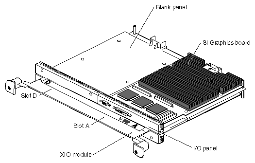
Follow the instructions in this section to remove both graphics boards, and place the secondary SI graphics board in slot A.
Go to Chapter 1, “Preparing the Workstation to Install the OCTANE/SI Board” and follow the directions through removing the XIO module. Then return here and go to the next step.
Place protective caps on the XIO compression connectors on the graphics boards. Caps came with the OCTANE workstation.
Determine where on your desk you will place each board, so you can determine which board was in which slot.
Remove the four screws that hold the SI graphics board in slot A to the XIO module.
Lift the graphics board off the XIO module, and place it on an clean, dry, antistatic surface. Your desktop works well.
Turn the XIO module so that the secondary graphics board faces you.
Follow steps 4 and 5 to remove the second graphics board.
Place the secondary graphics board into slot A.
Replace the four screws.
Turn the XIO module so you are facing the empty slot that held the secondary graphics board.
Place a blank panel in the slot that held the secondary graphics board.
Replace the four screws.
Remove the caps from the compression connectors.
Go to “Replacing the XIO Module” and follow the directions for replacing the XIO module through powering on the workstation. Then return here and go to the next section for instructions on checking and diagnosing the configuration.
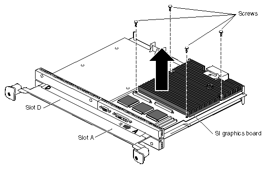
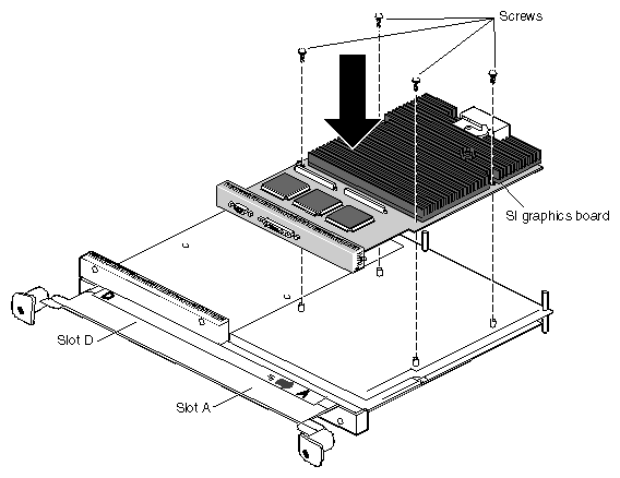
Table 5-2. Diagnostic Test Results - SI/SI or SI with texture memory board/SI Configuration
| State of secondary graphics board in the primary graphics board slot |
|
|---|---|---|
1. The primary head displayed a blank or faulty image. | The secondary head displayed a blank or faulty image. | Software problem; call your authorized service representative. |
2. The primary head worked properly. | The secondary head works properly. | Software problem; call your authorized service representative. |
3. The primary head displayed a blank or faulty image. | The secondary head works properly. | Primary graphics board may be faulty; call your authorized service representative. |
4. The primary head worked properly. | The secondary head displays a blank or faulty image. | Secondary graphics board may be faulty; call your authorized service representative. |
After performing this diagnostic test, return the graphics boards to their original positions. Follow the directions in this section.
Go to Chapter 1, “Preparing the Workstation to Install the OCTANE/SI Board” and follow the directions through removing the XIO module. Then return here for instructions on returning the graphics boards to their original positions.
Place caps on the compression connectors.
Remove the graphics board from slot A. In an SI/SI configuration, place the SI graphics board on your desk so you can determine which of the SI boards was removed from which slot.
Remove the four screws holding the graphics board to the XIO module.
Lift the board off the XIO module and place it on a clean, dry, antistatic surface.
Turn the XIO module until you are facing the secondary graphics board.
Remove the second SI graphics board from its slot.
Remove the four screws holding the graphics board to the XIO module.
Lift the board off the XIO module.
Place the board from slot A into the slot that held the secondary graphics board.
Insert and tighten the four screws that hold the board to the XIO module.
Repeat the installation process into slot A for the other SI graphics board.
Remove the caps from the compression connectors.
Go to “Replacing the XIO Module” and follow the directions for replacing the XIO module through powering on the workstation. Then call your authorized service representative with the results of your diagnostic test.
The diagnostic test for the OCTANE workstation with a SSI/SI or MXI/SI configuration is different from a SI/SI or SI with texture memory option board/SI configuration.
You cannot swap the heads in an SSI/SI or MXI/SI configuration. However, you can place the secondary head in slot A to see if it is recognized.
Follow the instructions in this section to remove both graphics boards, and place the SI graphics board in slot A.

Go to Chapter 1, “Preparing the Workstation to Install the OCTANE/SI Board” and follow the directions through removing the XIO module. Then return here and go to the next step.
Place protective caps on the XIO compression connectors on the graphics boards. Caps came with the OCTANE workstation.
Turn the XIO module so that slots D and A (the SSI or MXI graphics board) are facing you.
Remove the six screws that hold the SSI or MXI graphics board to the XIO module.
Place the SSI or MXI graphics board on an clean, dry, antistatic surface. Your desktop works well.
Turn the XIO module so that the secondary graphics board faces you.
Remove the four screws that hold the secondary SI graphics board to the XIO module.
Place the secondary SI graphics board on an clean, dry, antistatic surface. Your desktop works well.
Place a blank panel in the slot from which you removed the secondary graphics board.
Insert and tighten the four screws that hold the blank panel to the XIO module.
Place the secondary SI graphics board into slot A.
Replace the four screws.
Remove the compression connector cap.
Place a blank panel slot D (that also held the primary graphics board), using four screws to attach the blank panel to the XIO module.
Caution: Do not place the SSI or MXI graphics board in slots B and C. Go to “Replacing the XIO Module” and follow the directions for replacing the XIO module through powering on the workstation. Then go to the next section to check and diagnose the configuration.

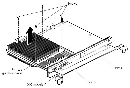
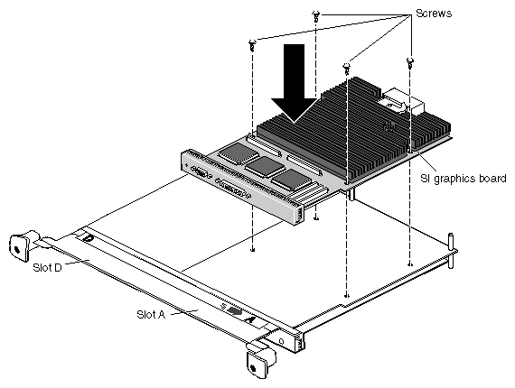
Table 5-3. Diagnostic Test Results - SSI/SI or MXI/SI Configuration
| State of secondary graphics board in the primary graphics board slot |
|
|---|---|---|
1. Primary head displayed a blank or faulty image. | The secondary head displayed a blank or faulty image. | Software problem; call your authorized service representative. |
2. Primary head worked properly. | The secondary head works properly. | Software problem; call your authorized service representative. |
3. The primary head displayed a blank or faulty image. | The secondary head works properly. | Primary graphics board is faulty; call your authorized service representative. |
4. The primary head worked properly. | The secondary head displays a blank or faulty image. | Secondary graphics board is faulty; call your authorized service representative. |
After performing this diagnostic test, return the graphics boards to their original positions. Follow the directions in this section.
Go to Chapter 1, “Preparing the Workstation to Install the OCTANE/SI Board” and follow the directions through removing the XIO module. Then return here for instructions on returning the graphics boards to their original positions.
Place caps on the compression connectors.
Remove the secondary graphics board from slot A.
Remove the four screws holding the SI graphics board to the XIO module.
Lift the board off the XIO module and place it on a clean, dry, antistatic surface.
Remove the blank panel from slot D.
Place the SSI or MXI graphics board into slots D and A.
Insert and tighten the six screws that hold the board to the XIO module.
Find the blank panel that is a place holder for the secondary graphics board, and remove the four screws holding the blank panel to the XIO module.
Remove the blank panel from the slot into which you want to place the secondary graphics board.
Remove the four screws holding the blank panel to the XIO module.
Lift the blank panel off the XIO module.
Place the secondary SI graphics board in the empty slot.
Insert and tighten the fours screws that attach the secondary SI graphics board to the XIO module.
Remove the caps from the compression connectors.
Go to “Replacing the XIO Module” and follow the directions for replacing the XIO module through powering on the workstation. Then call your authorized service representative with the results of your diagnostic test.