In most cases, the protocol parameter files that SX.25 provides are appropriate for X.25 WANs and LANs, so it is not necessary to create customized parameter files. However, if you determined that the settings in the factory-shipped parameter files do not meet your connection requirements (see “Evaluating SX.25 Parameter Files” in Chapter 2 for details), you need to perform the procedures in this chapter. These procedures explain how to use factory-shipped files as templates to create your own custom parameter files.
 | Note: Factory-shipped SX.25 parameter files cannot be modified. To create a custom file, you open a factory-shipped file, make your changes, and save them in a new file under a different name. |
This chapter contains three procedures for creating configuration files:
The contents of X.25, LAPB, and LLC2 parameter files are displayed in a series of windows that you use as templates to create custom parameter files. Each template contains a logical grouping of protocol parameters (such as LLC2 timer parameters) and input widgets for specifying custom settings (such as option menus and sliders). In addition, the lower of edge of a template contains tabs and buttons for controlling the file creation process.
Click these topics to view information about parameter window tabs and buttons:
When you open a protocol parameter file, the General parameters tab is displayed. Use the labeled tabs at the lower edge of the window to display a different group of parameters. If the parameters that you wish to display do not appear on a labeled tab, move the pointer to the unlabeled tab area and use the right mouse button to select a tab from a pull-down list, as shown in Figure 7-1.

Use the OK button to record changed settings in a previously-created custom parameter file. (You cannot use OK to write to a factory-shipped file; see “The Save As Button.”). Clicking OK confirms your changes and closes the custom file, but it does not save the modified version of the file. The modified parameter file is permanently saved when you save the configuration file (normally, this is done at the end of the port configuration procedure).
Use the Save As button to record your changes to a factory-shipped file in a custom parameter file. When you click Save As, you are prompted to enter a name for the new custom file. Entering a name for the new custom file does not save it. The file is permanently saved when you save the configuration file (normally, this is done at the end of the port configuration procedure).
Use the Cancel button to close the parameter file and discard your entries. When you click Cancel, no changes are made to the parameter file; any information that was in the file from previous sessions remains unchanged.
Use the procedure below to create a custom X.25 parameter file for a WAN or LAN port. This procedure assumes that you completed steps 1 through 3 of either “Creating a WAN Port Configuration Record” (for WAN ports) or “LAN Port Configuration Procedure” (for LAN ports) in Chapter 4. It also assumes that you plan to use a factory-shipped file as a template for the custom file, but you can also use a previously-created custom file as a template.
Open a factory-shipped X.25 parameter file.
To open a factory-shipped file, select a file from the X.25 Parameter Files list, based on the port's function as DTE or DCE equipment and on the X.25 recommendation implemented on the network. Click the Open button (or double-click on the file) to display file contents. Click on the labeled tabs at the bottom of the window to view additional parameter settings. To view an unlabeled tab, move the pointer to the unlabeled area and use the right mouse button to select a tab from a pull down list (see Figure 7-1).
Modify the settings that need changing.
The contents of X.25 parameter files comprise several windows. Figure 7-2 through Figure 7-13 illustrate X.25 protocol parameters and their factory-shipped settings; see the information that follows each figure for information about the parameters that the figure contains. Use the values specified by your network service provider or your knowledge of the operating characteristics of your network to change X.25 parameter settings. When you finish your changes, return to step 3 of this procedure.
Create a new X.25 parameter file under a different name to save your settings.
You cannot modify the original X.25 parameter file, but you can create a modified version of the original file and save it under a different name. To save your changes to X.25 parameter settings, click the Save As button; then, enter the name of the new file in the filename dialog box.
Notice that the new X.25 file appears in the X.25 Parameter Files list and that the new file is selected.
Return to step 5 of “Creating a WAN Port Configuration Record” or “LAN Port Configuration Procedure” in Chapter 4 to continue the configuration process.
Figure 7-2 illustrates the panel of general operating parameters for X.25. Each parameter is explained in the information that follows the figure.
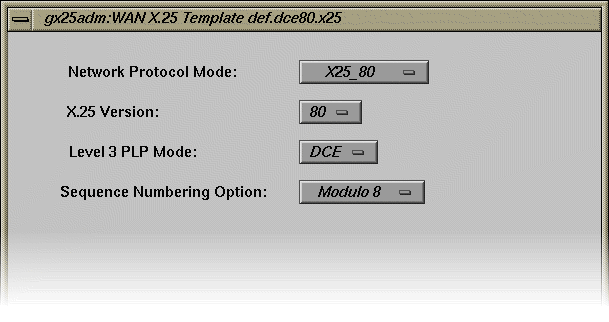
Figure 7-3 illustrates the panel of logical channel parameters for X.25 and their default settings. Channel parameters are explained in the information that follows the figure.
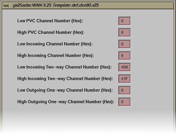
In a DTE/DTE environment, one DTE sees the range of lowest incoming logical channels as presented in Figure 7-3. The other DTE sees these ranges from the viewpoint of a DCE. For example, it views the range from lowest incoming logical channels to highest incoming logical channels as one-way outgoing.
The numbers of logical channels of each type are calculated from the values of the pairs of parameters:
Number of PVCs = Highest PVC - Lowest PVC + 1
| Note: If highest and lowest logical channels are both set to zero, no channels are allocated in that grouping. |
These parameters specify logical channel functions:
| Low and High PVC Channel Number |
| |
| Low and High Incoming Channel Number |
| |
| Low and High Two-way Channel Number |
| |
| Low and High Outgoing Channel Number |
|
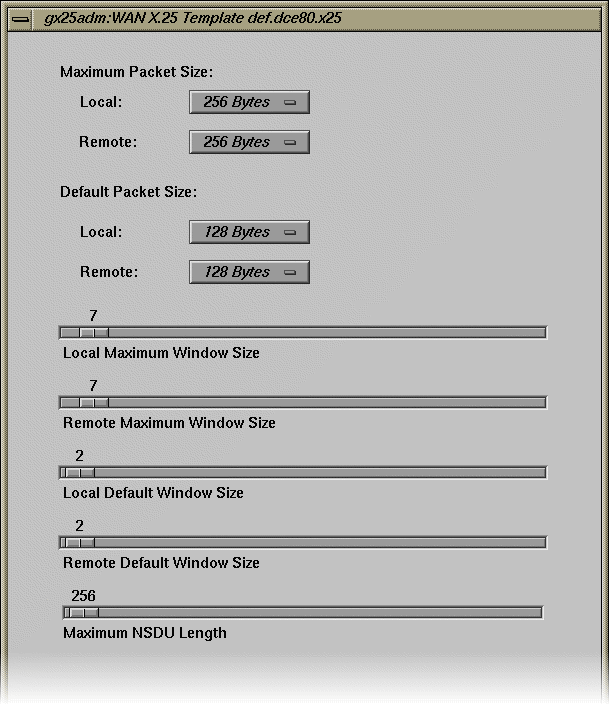
Figure 7-4 illustrates the panel of packet-size and window-size parameters for X.25. Each parameter is explained in the information that follows the figure.
| Local and Remote Maximum Packet Size |
Use these parameters to set the maximum size of data packets that are acceptable on the X.25 link. On any incoming call, a value for the packet-size parameter greater than the lowest outgoing logical channel (shown in Figure 7-3) or remote maximum packet size is negotiated down to this value when the call is accepted.
| |||
| Local and Remote Default Packet Size |
Use this parameter to specify the default packet size for a particular network. The standard value is 7, which sets a default data packet size for each direction of transmission to 128 octets (27, that is, 1 << 7). The value may be nonstandard if it is agreed between all communicating parties on the LAN or between the DTE and DCE. | |||
| Local and Remote Maximum Window Size |
Use this parameter to specify the maximum window size acceptable on the subnetwork. On any incoming call, a window size value greater than lowest outgoing logical channel (shown in Figure 7-3) or remote maximum window size is negotiated down to this value when the call is accepted. For Modulo 8 networks, the range for lowest outgoing logical channel or remote maximum window is 2 through 7, and for Modulo 128 the range is 2 through 127. | |||
| Local and Remote Default Window Size |
Use this parameter to specify the value of the default window size for a particular network. The standard value is 2. The value may be nonstandard provided it is agreed between all communicating parties on the LAN, or between the DTE and DCE.
| |||
| Maximum NSDU Length |
|
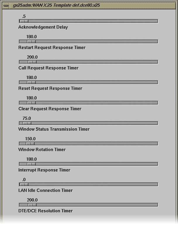
Figure 7-5 illustrates the tab of timer parameters for X.25. Notice that timer parameter names are descriptive of their function. For parameters known by a mnemonic equivalents, the mnemonic is given in parentheses in the descriptions that follow. All timer values are measured in tenths of a second except where noted.
| Acknowledgement Delay | | |
| Restart Request Response Timer |
| |
| Call Request Response Timer |
| |
| Reset Request Response Timer |
| |
| Clear Request Response Timer |
| |
| Window Status Transmission Timer |
The default value is 75, the permitted range 0 to 3200. | |
| Window Rotation Timer |
| |
| Interrupt Response Timer |
| |
| LAN Idle Connection Timer |
The default LAN value is 60; the default WAN value is 0. For both, the permitted range is 0 to 3200. | |
| Resolution Timer |
The default value is 200; the permitted range 0 to 3200. |
Figure 7-6 illustrates the panel of counters parameters for X.25. Each parameter is explained in the information that follows the figure.
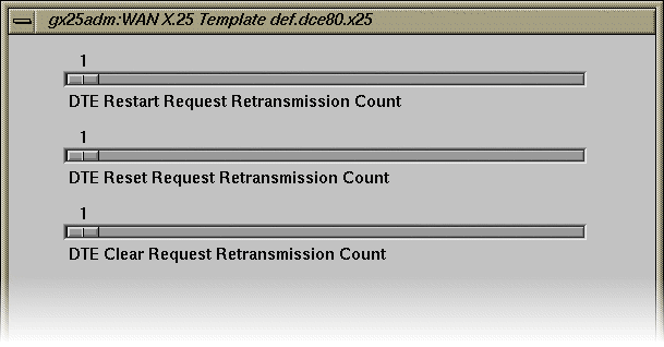
| DTE Restart Request Retransmission Count |
| |
| DTE Reset Request Retransmission Count |
| |
| DTE Clear Request Retransmission Count |
|
Figure 7-7 illustrates the panel of transit delay parameters for X.25. Each parameter is explained in the information that follows the figure.
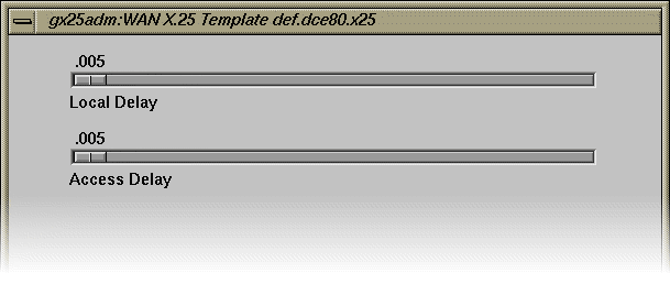
| Local Delay | Specifies the transit delay that results from internal processing. | |
| Access Delay | Specifies the transit delay that results from the line transmission rate. The default for both parameters is .005; the permitted range 0 to 32. |
Figure 7-8 illustrates the panel of throughput class parameters for X.25. Each parameter is explained in the information that follows the figure.
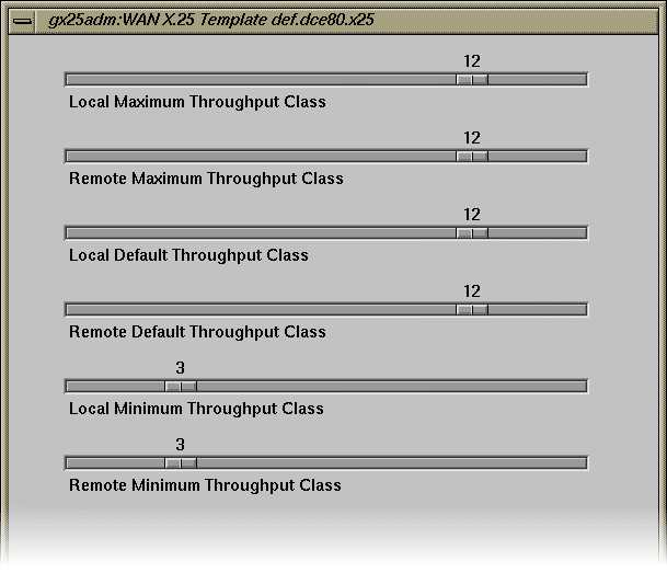
Be sure to observe the following points when you set these parameters:
The value of local maximum throughput class and remote maximum throughput class should be greater than or equal to that of local default throughput class and remote default throughput class, respectively.
The value of local default throughput class and remote default throughput class should be greater than or equal to that of local minimum throughput class and remote minimum throughput class, respectively.
| Local and Remote Maximum Throughput Class |
These parameters are the maximum supported value of the throughput class Quality Of Service parameter. ISO 8208 specifies a value for lowest outgoing logical channel (shown in Figure 7-3) or remote maximum throughput class in the range of 3 through 12, corresponding to a range of 75 to 48,000 bps. However, the supported valid range is 0 to 15. This accommodates nonstandard X.25 implementations that use the Throughput Class parameters to map to packet/window sizes (see “Throughput Window and Packet Parameters”). | |
| Local and Remote Default Throughput Class |
In some networks (TELENET, for example), negotiation of throughput class is towards a configured default throughput class. In such cases, the negotiate throughput class parameter (shown in Figure 7-13) is non-zero and lowest outgoing logical channel (shown in Figure 7-3) or remote default throughput class is the default. In other PSDNs, you should set lowest outgoing logical channel or remote default throughput class to the value of lowest outgoing logical channel or remote default throughput class. | |
| Local and Remote Minimum Throughput Class |
According to ISO 8208, the throughput class parameter is defined in the range of 3 through 12. Some PSDNs may provide a different mapping, in which case lowest outgoing logical channel (shown in Figure 7-3) or remote minimum throughput class is the minimum value. |
Figure 7-9 illustrates the panel of closed user group (CUG) parameters for X.25. To change a CUG parameter, click the check box beside it to turn the parameter on or off. Use the option menu beside the ``CUG Format'' parameter to select either basic or extended CUG format.
| Note: Some networks, such as DDN, require you to set the flag to reject incoming calls carrying any closed user group optional facility. |
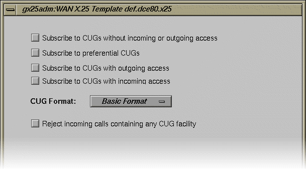
Figure 7-10 illustrates the panel of subscription option parameters for X.25. To change a subscription parameter, click the check box beside it to turn the parameter on or off.
| Note: Subscribing to extended call packets enables window- and packet-size negotiation, which permits the exchange of extended call packets. Treating extended incoming call packets as a procedure error prevents the exchange of extended call packets. |
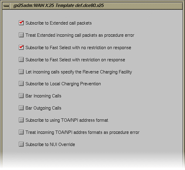
Figure 7-11 illustrates the panel of localization parameters for X.25, which are used to tune options for a particular subnetwork. Each parameter is explained in the information that follows the figure.
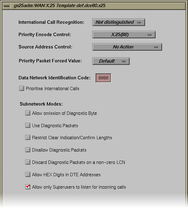
| International Call Recognition |
| |
| Priority Encode Control |
| |
| Source Address Control |
| |
| Priority Packet Forced Value |
| |
| Data Network Identification Code |
| |
| Prioritize International Calls |
| |
| Subnetwork Modes |
|
The X.25 standard does not give specific recommendations for handling the D-bit. To provide flexibility to accommodate local PSDN requirements, SX.25 lets you specify how the D-bit should be handled. Figure 7-12 illustrates the panel of D-bit control parameters for X.25. Each parameter is explained in the information that follows the figure.
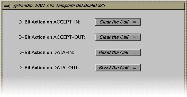
Use the popup option menu beside each D-bit control parameter to select a new value for the parameter. Your choices for D-bit parameters are Clear the Call, Zero the D-bit, or No Action.
| D-Bit Action on ACCEPT-IN |
| |
| D-Bit Action on ACCEPT-OUT |
| |
| D-Bit Action on DATA-IN |
| |
| D-Bit Action on DATA-OUT |
|
Some implementations of X.25 do not use the X.25 packet and window negotiation function. Instead, these implementations use throughput class window and packet mapping to determine window and packet sizes. Figure 7-13 illustrates the panel of X.25 throughput class parameters. Each parameter is explained in the information that follows the figure.
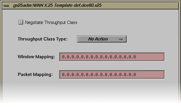
| Negotiate Throughput Class |
Click on the check box to set this parameter on for networks like TELENET, which require negotiation of the throughput class towards those defaults. When this parameter is off (the default), throughput class is negotiated according to the X.25 procedures instead. | |
| Throughput Class Type |
Keep these points in mind when setting this parameter:
| |
| Window Mapping |
| |
| Packet Mapping |
|
These are the last X.25 parameters. Return to step 3 of “Creating a LAPB Parameter File” to continue the file creation process.
Use the procedure in this section to create a custom LAPB parameter file. This procedure assumes that you completed steps 1 through 6 of “Creating a WAN Port Configuration Record” in Chapter 4. It also assumes that you plan to use a factory-shipped file as a template for the custom file, but you can also use a previously-created custom file as a template.
Open the factory-shipped LAPB parameter file.
To open a factory-shipped file, select the file from the LABP Parameter File list and click the Open button (or double-click on the file) to display its contents. Click on the labeled tabs at the bottom of the window to view additional parameter settings.
Modify the settings that need changing.
The contents of the LAPB parameter file comprise several windows. Figure 7-14 through Figure 7-16 illustrate LAPB protocol parameters and their factory-shipped settings; see the information that follows each figure for information about the parameters that the figure contains. Use the values specified by your network service provider or your knowledge of the operating characteristics of your network to change LAPB parameter settings. When you finish your changes, return to step 3 of this procedure.
Create a new LAPB parameter file under a different name to save your settings.
You cannot modify the original LAPB parameter file, but you can create a modified version of the original file and save it under a different name. To save your changes to LAPB parameter settings, click the Save As button; then, enter the name of the new file in the filename dialog box.
Notice that the new file LAPB appears in the LAPB Parameter Files list and that the new file is selected.
Return to step 8 of “Creating a WAN Port Configuration Record” to continue with the port configuration process.
Figure 7-14 illustrates the panel of general operating parameters for LAPB. Each parameter is explained in the information that follows the figure.
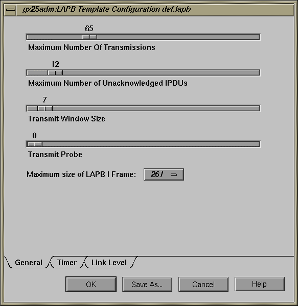
| Maximum Number of Transmissions |
The default value is 65 and the permitted range is 1 to 255. | |
| Maximum Number of Unacknowledged IPDUs | The default value is 12 and the permitted range is 0 to 127. | |
| Transmit Window Size |
In normal mode, when Modulo 8 sequence numbering is used, the default value is 7 and the permitted range is 1 to 7. In extended mode when Modulo 128 sequence numbering is used, the default value is 7 and the permitted range is 1 to 127. | |
| Transmit Probe |
In normal mode when Modulo 8 sequence numbering is used, the default value is 0 and the permitted range is 0 to 7. In extended mode, when Modulo 128 sequence numbering is used, the default value is 0 and the permitted range is 0 to 127. | |
| Maximum Size of LAPB I frame | maximum X.25 data size + X.25 protocol length + LAPB protocol length The default value is 261. Permitted values are: 261 to 263, 517 to 519, 1029 to 1031, 2053 to 2055, and 4101 to 4103. |
Figure 7-15 illustrates the panel of timer parameters for LAPB. Each parameter is explained in the information that follows the figure. Unless noted otherwise, LAPB timer values are expressed in tenths of a second.
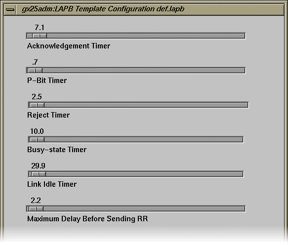
| Acknowledgement Timer |
The default value is 7.1 and the permitted range is .1 to 300. | |
| P-Bit Timer |
The default value is .7 and the permitted range is .1 to 300. | |
| Reject Timer |
The default value is 2.5 and the permitted range is .1 to 1000. | |
| Busy-state Timer |
The default value is 10.0 and the permitted range is .1 to 3000. | |
| Link Idle Timer |
The default value is 29.9 and the permitted range is 0 to 3200. | |
| Maximum Delay Before Sending RR |
The default value is 2.2 and the permitted range is 0 to 300. |
Figure 7-16 illustrates the panel of link-level parameters for LAPB.
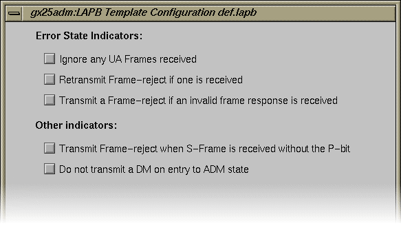
| Error State and Other Indicators |
|
These are the last LAPB parameters. Return to step 3 of “Creating a LAPB Parameter File” to complete the file creation process.
Use the procedure below to create a custom LLC2 parameter file. This procedure assumes that you completed steps 1 through 5 of the “LAN Port Configuration Procedure” in Chapter 4. It also assumes that you plan to use a factory-shipped file as a template for the custom file, but you can also use a previously-created custom file as a template.
Open the factory-shipped LLC2 parameter file.
To open a factory-shipped file, select the file from the LLC2 Parameter File list that is appropriate for the type of media on the LAN where this port will connect. Click the Open button (or double-click on the file) to display file contents. Click on the labeled tabs at the bottom of the window to view additional parameter settings.
Modify the settings that need changing.
The contents of the LLC2 parameter file comprise several windows. Figure 7-17 through Figure 7-19 illustrate LAPB protocol parameters and their factory-shipped settings; see the information that follows each figure for information about the parameters that the figure contains. Use the values specified by your network service provider or your knowledge of the operating characteristics of your network to change LLC2 parameter settings. When you finish your changes, return to step 3 of this procedure.
Create a new LLC2 parameter file under a different name.
You cannot modify the original LLC2 parameter file, but you can create a modified version of the original file and save it under a different name. To save your changes to LLC2 parameter settings, click the Save As button; then, enter the name of the new file in the filename dialog box.
Notice that the new file LLC2 appears in the LLC2 Parameter Files list and that the new file is selected.
Return to step 8 of “LAN Port Configuration Procedure” to complete the port configuration process.
Figure 7-17 illustrates the panel of general operating parameters for LLC2, which are the same for all media types. Each parameter is explained in the information that follows the figure.

| Maximum Number of Transmissions |
The default value is 10 and the permitted range is 1 to 255. | |
| Maximum Number of Unacknowledged IPDUs | The default value is 3 and the permitted range is 0 to 127. | |
| Transmit Window Size |
The default value is 7 and the permitted range is 1 to 127. | |
| Transmit Probe |
The default value is 0 and the permitted range is 0 to 127. | |
| Maximum Size of LLC2 I frame | maximum X.25 data size + X.25 protocol length + LLC protocol length The default value is 263. Permitted values are: 263 to 264, 519 to 520, and 1031 to 1032. |
Figure 7-18 illustrates the panel of timer parameters for LLC2, which are the same for all media types. Each parameter is explained in the information that follows the figure. Timer parameters are expressed in tenths of a second unless otherwise noted.
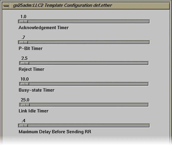
| Acknowledgement Timer |
The default value is 1.0 and the permitted range is .1 to 300. | |
| P-Bit Timer |
The default value is .7 and the permitted range is .1 to 300. | |
| Reject Timer |
The default value is 2.5 and the permitted range is .1 to 1000. | |
| Busy-state Timer |
The default value is 10.0 and the permitted range is 0 to 3000. | |
| Link Idle Timer |
The default value is 25.0 and the permitted range is 0 to 3200. | |
| Maximum Delay Before Sending RR |
The default value is .4 and the permitted range is 0 to 300. |
Figure 7-19 illustrates the panel of XID parameters for LLC2, which are the same for all media types. Each parameter is explained in the information that follows the figure.

| XID Window Size |
The default value is 7 and the permitted range is 1 to 127. | |
| Duplicate MAC XID Count |
The default value is 0and the permitted range is 0 to 255. | |
| Duplicate MAC XID Timer |
The default value is .5 and the permitted range is 0 to 300. |
These are the last LLC2 parameters. Return to step 3 of “Creating an LLC2 Parameter File” to complete the file creation process.