There is 48 VDC is present on the system midplane. This voltage is present even if the system has been reset or halted.
 | Caution: The Onyx system can weigh over 1000 pounds when fully configured. Use at least two people when moving the system chassis, and take care to ensure that the system does not tip or become unbalanced. Two people should also be used to move the monitors. Be sure to practice proper lifting techniques. |
Customer maintenance is limited to the outside of the chassis, which comprises the peripherals and cables attached to the I/O panel. No user-serviceable parts are found within the chassis.
 | Note: This product requires the use of external shielded cables in order to maintain compliance with Part 15 of the FCC rules. |
A high-resolution, 1600 x 1200-pixel 21-inch monitor ships as the standard monitor for the Onyx RE2 deskside systems. An optional 20-inch graphics monitor is also available with certain system configurations. This section describes how to install the 21- and 20-inch monitors. Connect the monitor you received by following the steps in the applicable section.
| Caution: Before plugging any monitor into either a 110 VAC or a 220–240 VAC outlet, be sure that the electrical rating on the label is in either the 110 or the 220–240 range, whichever applies. |
When using a monitor in locations that do not have either of these outlets, contact your Silicon Graphics system support engineer before plugging in the monitor power cable.
| Note: If your monitor has white switches below the RGB posts, make sure they are pressed in so that they are in the 75-ohm position; otherwise, the monitor displays the wrong colors. |
Use only the cables specified to connect the monitor to the Onyx deskside chassis.
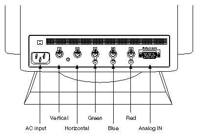
The RE2 graphics system uses a 21-inch, high-resolution monitor. This monitor uses either a 13W3-to-BNC connector cable or a 13W3-to-13W3 cable. Connect the 13W3 fitting to the I/O panel and the BNC connectors to the back of the monitor. See Figure 3-1 for an example of the connectors on the 21-inch monitor. See Figure 3-2 for a cable connection example.
When the system is booted, the monitors will operate in their default resolution of 1280 x 1024. To change the default video format, you must use the setmon command. For more information about the setmon command options, see the setmon reference (man) page.

The video cable for the 20-inch monitor has two 13W3 connectors on each end (see Figure 3-3).
Plug the male end of the monitor power cable into either the United States standard 110 VAC outlet (NEMA 5-15R) or the Continental European 250 VAC, 16A type CEE 7/7 outlet, whichever is appropriate. Then proceed with connecting the video cable.
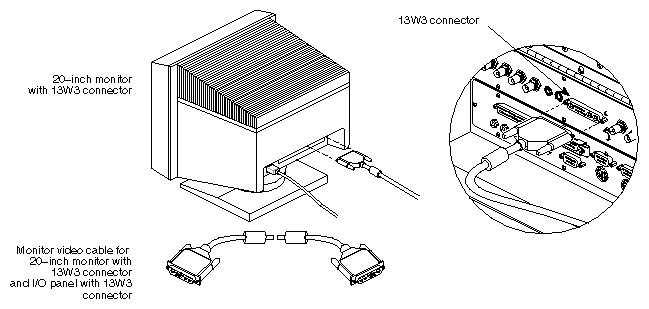
Find the monitor video cable. This cable has large 13W3 connectors on each end. See Figure 3-4.
Attach one end of the monitor video cable to the 13W3 connector on the back of the monitor. Secure the screws on either side of the connector.
Attach the other end of the monitor video cable to the deskside system's I/O panel. Secure the screws on either side of the connector.

Figure 3-5 shows the front control locations for the 21-inch color monitor. Table 3-1 describes the 21-inch monitor controls and Table 3-2 describes the 21-inch monitor viewing mode adjustments. Table 3-3 shows the preset viewing modes for the 21-inch monitor.

| Note: The 21-inch model has 7 factory-set viewing modes (see Table 3-3) and memory for an additional 23 configurable settings. The 20-inch model also has factory-set modes (see Table 3-5) and cconfigurable settings. |
Table 3-1. 21-Inch Monitor Controls
Control | Description |
|---|---|
Signal Input Selection | Selects BNC or 15-pin mini-D connectors. |
Manual/Auto Selection button | Manual position allows display size and position to be changed using the Store, Selection, and Adjustment controls. The Auto position selects one of the seven factory-preset viewing modes. |
Store button | With the Manual/Auto Selection button in the Auto position, pressing this button steps through the preset viewing modes. With the Manual/Auto Selection button in the Manual position, pressing this button stores the displayed viewing mode. This mode is indicated when one of the adjustment LEDs lights. |
Selection button | With the Manual/Auto Selection button in the Manual position, pressing this button steps through the four available adjustments (horizontal size and position, vertical size and position). When the adjustment is active, the corresponding amber LED lights. |
Adjustment button (–) | Pressing this button, with either the horizontal or vertical size adjustment selected, decreases screen size. With the horizontal position adjustment selected, pressing this button shifts the screen position to the left. With the vertical position adjustment selected, pressing this button shifts the screen down. |
Adjustment button (+) | Pressing this button, with either the horizontal or vertical size adjustment selected, increases screen size. With the horizontal position adjustment selected, pressing this button shifts the screen position to the right. With the vertical position adjustment selected, pressing this button shifts the screen up. |
Power Switch | Press on/press off switch. When power is on, the green LED in the switch lights. |
Contrast control (half moon icon) | Turn to adjust foreground brightness. |
Brightness control (sun icon) | Turn to adjust background brightness. |
Degaussing button | Press to manually degauss monitor (monitor automatically degausses following power on). |
Three video signal termination buttons (located on rear panel) | Press in when installing a single monitor (to provide 75-ohm termination). Release buttons when connecting multiple monitors with loop-through (provides higher impedance). |
Sync Adjustment button (located on rear panel) | Release the button to adjust the incoming sync signal manually. |
Table 3-2. 21-Inch Monitor Viewing Mode Adjustments
Active (Lit) Adjustment Button | Minus (–) | Plus (+) |
|---|---|---|
Horizontal size | Decrease screen size | Increase screen size |
Horizontal position | Shift screen left | Shift screen right |
Vertical size | Decrease screen size | Increase screen size |
Vertical position | Shift screen down | Shift screen up |
Table 3-3. Preset Viewing Modes for 21-Inch Monitor
Mode Number | Video Mode | Horizontal Frequency | Vertical | Resolution |
|---|---|---|---|---|
1 | VGA350 | 31.5 kHz | 70 Hz | 640 x 350 |
2 | VGA400 | 31.5 kHz | 70 Hz | 640 x 400 |
3 | VGA480 | 31.5 kHz | 60 Hz | 640 x 480 |
4 | 8514/A | 35.5 kHz | 87 Hz | 1024 x 768 (interlaced) |
5 | 1024 x 768 | 48.8 kHz | 60 Hz | 1024 x 768 |
6 | 1152 x 870 | 63.5 kHz | 70 Hz | 1152 x 870 |
7 | 1152 x 870 | 68.7 kHz | 75 Hz | 1152 x 870 |
Table 3-4 describes the 20-inch monitor controls. Note that the remote control (remote commander) must be used within 19.75 inches (50 cm) of the monitor's front.
Table 3-4. 20-Inch Monitor Controls
Control | Description |
|---|---|
Power switch (front mounted) | Turns the monitor on and off. |
Contrast control (front mounted) | Two buttons (+ and –) are used to adjust foreground brightness. |
| Note: The following controls are located on the pull-out remote control. |
BRIGHT (brightness) | Press + to increase the picture brightness. Press – to decrease it. |
V-CENT (vertical centering) | Press + to move the picture upward. Press the – to move the picture down. |
V-SIZE (vertical size) | Press + to increase the vertical size. Press the – to decrease it. |
V-STAT (vertical static convergence) | You can adjust the vertical static convergence so the colors converge at the center of the picture. Press + to move red upward and blue down. Press – to move red down and blue upward. |
TILT | Press the right button to tilt the picture clockwise. Press the left button to tilt the picture counterclockwise. |
COLOR TEMP (temperature) | Select proper signal color temperature. H=9300 K (factory default); M=6500 K; L=5000 K |
CONTR (contrast) | Press + to increase contrast, or press – to decrease contrast. |
H-CENT (horizontal centering) | Press + to move the picture to the right, press – to move it to the left. |
H-SIZE (horizontal size) | Press + to increase the horizontal size. Press – to decrease the horizontal size. |
H-STAT (horizontal static convergence) | You can adjust the horizontal static convergence until the colors converge at the center of the picture. Press + to move blue to the left and red to the right. Press – to move blue to the right and red to the left. |
Reset (button) | Pressing the button resets every user-stored data adjustment to the factory-preset level for the input signal being received. Note that you cannot reset the user-stored adjustment data item by item. |
Table 3-5. Preset Viewing Modes for 20-Inch Monitor
Mode Type | Resolution | Horizontal Frequency | Vertical |
|---|---|---|---|
1 | 1024 x 768 | 48.5 kHz | 59.6 Hz |
2 (non stereo) | 1280 x 1024 | 63.9 kHz | 60 Hz |
3 (stereo) | 1280 x 492 | 63.9 kHz | 119.88 Hz |
4 | 1280 x 1024 | 76.9 kHz | 72.3 Hz |
5 | 1280 x 512 | 65.05 kHz | 120.05 Hz |
6 (default) | 1280 x 1024 | 81.967 kHz | 75.966 Hz |
7 | 1280 x 1024 | 53.249 kHz | 50 Hz |
The following procedure is used to adjust the monitor's screen geometry when the monitor is experiencing problems with the vertical sync.
| Note: Do not use this button unless there is a problem with the incoming sync signal. |
Select the Manual mode by pushing in the Manual/Auto Selection button.
Push out the Sync Adjustment button (located at the rear of the monitor).
If the monitor is out of sync or there is no display with the correct input signal, press the “+” Adjustment button repeatedly until the displayed image is correct.
Note: Both the Adjustment buttons change the screen geometry in single increments. Each time a button is pressed, the screen geometry is changed by one increment. Holding a button in will not cause a continuous change in the screen geometry. When the screen geometry is correct, press the Adjustment button one more time.
If the monitor displays partial skew (the top of the screen appears to tear to the right), press the “–” Adjustment button repeatedly until the displayed image is correct.
When the vertical sync is correct, push in the Sync Adjustment button to the off position.
If the size and position of the displayed image is incorrect, use the Selection button to activate the required adjustment (the corresponding LED will light), and the “+” and “–” adjustment buttons to correct the screen geometry.
Press the Store button to save the adjustments in the monitor's memory.
Push out the Manual/Auto Selection button to return to “Auto” mode.
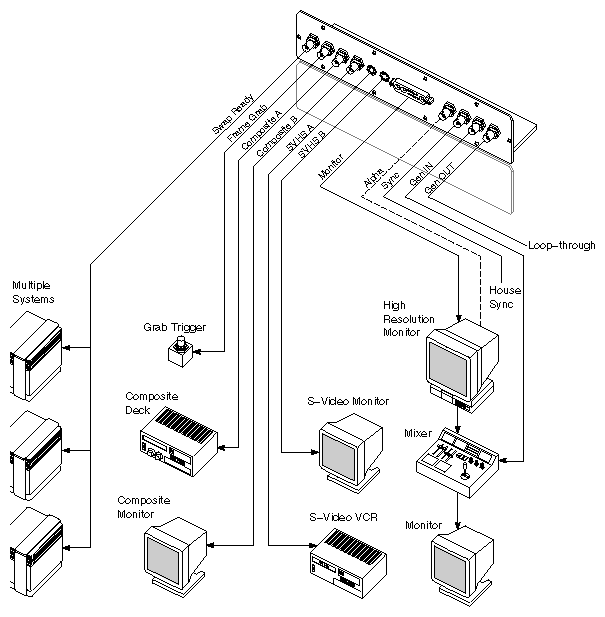
The graphics subsystems installed on your system are connected to a variety of video peripherals through the graphics I/O panel connectors. In addition to a high-resolution color monitor, the following peripherals can be connected:
Composite Video Monitor
Composite VCR
Frame Grab Trigger
Super VHS Monitor
Super VHS VCR
Video Mixer
| Caution: You must use the appropriate video peripherals. The composite video ports are connected to video monitors and VCRs that operate in NTSC or PAL video format. The S-Video ports connect to equipment that uses Super VHS format. |
A typical configuration, showing the graphics subsystem ports and peripherals, is shown in Figure 3-6.
Your system comes with a standard 101-key international keyboard. The keyboard has two identical plug receptacles, located in the upper right and left corners. These receptacles accepts the 6-pin mini-DIN connectors from either the keyboard cable or the mouse.
To install a keyboard:
Choose the side of the keyboard where the mouse will be located and insert the mouse cable connector into the nearest keyboard receptacle.
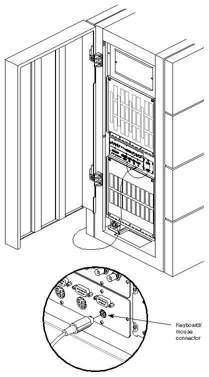
Attach one end of the keyboard cable to the remaining keyboard receptacle. Attach the other end of the keyboard cable to the keyboard connector on the main I/O panel (see Figure 3-7).
| Caution: Do not unplug the keyboard cable from the I/O panel while the system power is on; system damage can result. |
All Onyx rackmount systems are configured with a minimum of two fully independent SCSI channels provided by the IO4 board. In its maximum configuration, with the addition of multiple SCSI mezzanine boards, the Onyx rackmount graphics workstation can have 48 SCSI channels. A portion of these channels can be configured as either single-ended or differential SCSI.
The difference between single-ended and differential SCSI channels is defined as follows: a single-ended SCSI channel pairs each signal line with a ground line. Differential SCSI channels pair each signal line with a second signal that is the balanced inverse of the first. This configuration makes differential SCSI less susceptible to signal degradation due to noise and more suitable for remote (longer) cabling.
The IO4 board can communicate with both internal and external SCSI devices over either single-ended or differential SCSI channels. Generally, external SCSI channels are differential, and internal channels are single-ended. The requirements and limitations of both single-ended and differential SCSI channels are described below.
The maximum allowable length for single-ended (standard) SCSI cabling is 19.6 feet (6 meters). This maximum length reflects the combined lengths of both the internal and external cables. A single-ended SCSI bus can support a maximum of eight SCSI devices (including the SCSI controller board).
The maximum allowable length for differential SCSI is 80 feet (25 meters). As with single-ended SCSI, this length is the sum of both the internal and external cables. The differential SCSI bus supports a maximum of 16 devices (including the controller board).
| Note: The most common reason for SCSI device failure is insufficient noise margins due to exceeding the maximum cable length, cable impedance mismatches, or a combination of both. If you are having trouble with certain devices, particularly external devices, be sure to verify that you have not exceeded the maximum SCSI cable length. |
Always use the shortest cable possible. Route external cables away from potential damage due to foot traffic, cleaning, and so on.
If you have additional questions about SCSI connections and cable lengths, contact your Silicon Graphics representative.
SCSI channels must be terminated at both the IO4 board (or S mezz board) and at the last device on the channel. The internal SCSI channels (in the SCSIBoxes) are configured so that front loading devices (FLDs) can be added or removed without affecting the channel termination; however, if devices are being added or removed from an external SCSI bus, you must verify that the correct external channel termination is maintained.
| Caution: Single-ended and differential SCSI buses must be terminated with single-ended and differential terminators, respectively. Terminating a bus with the wrong terminator can cause system damage. |
| Caution: All installed IO4 boards and/or SCSI mezzanine boards are terminated at the time of installation. Do not attempt to open the cardcages to verify channel termination. |
This section describes the physical installation and removal of a front loading drive (FLD) from the Onyx workstation. It is assumed that the system has already been configured for the drives being removed or installed.
| Note: If the FLD is not configured, refer to Chapter 4, “Installing and Using Optional Peripherals,” for configuration instructions. |
Install an FLD in the SCSIBox drive enclosure as follows:
Ensure that the system power is turned off. If the system is running, refer to the “Powering Off the System” section, later in this chapter.
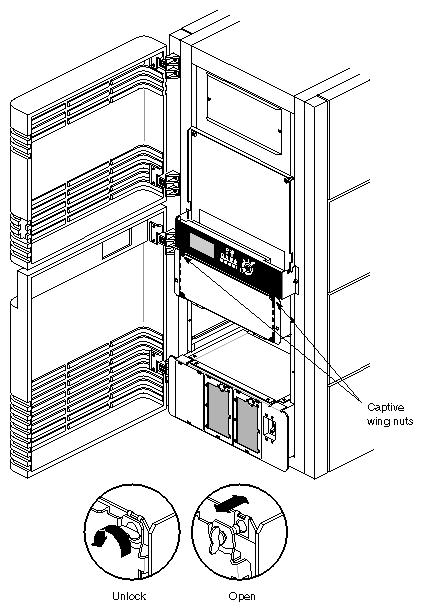
Open the lower front access door of the system chassis.
Release the two captive wing nuts securing the SCSIBox door and allow the door to swing down (see Figure 3-8).
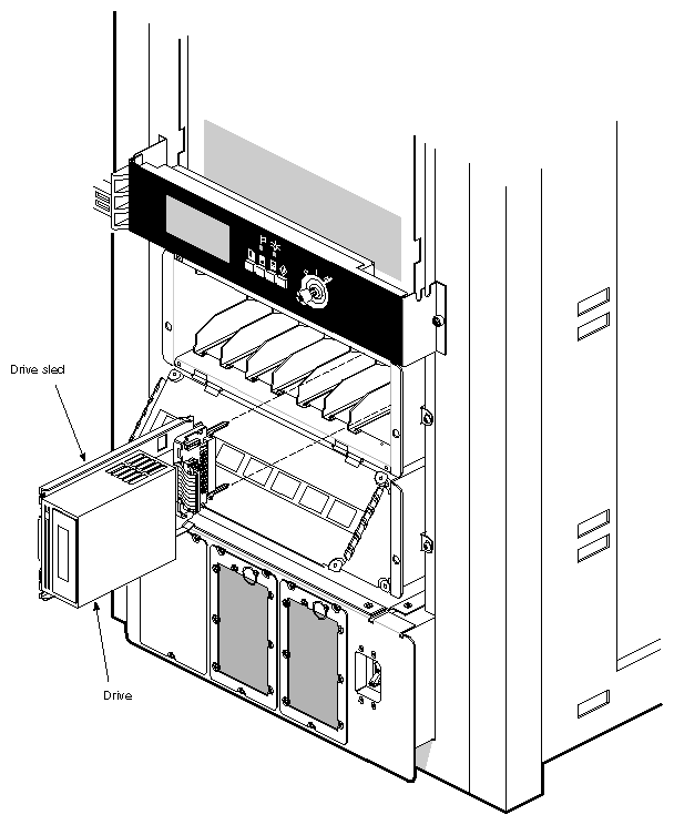
Orient the FLD relative to the SCSIBox so that the drive is facing toward the right (see Figure 3-9).
Select a vacant drive bay and carefully align the rails on the drive sled with the corresponding rails in the drive bay.
Slide the FLD into the bay until the locking mechanism is engaged and the locking lever on the drive sled moves down to the locked position. Push the lever down to ensure it is fully engaged.
Note: If the FLD is being installed for the first time, ensure that the drive is not terminated Verify that the device ID was not accidently changed during the installation.
Close the SCSIBox door.
Power on the system as described in the section entitled “Powering On the System.”
See the IRIX Advanced Site and Server Administration Guide for the information needed to configure the software.
Remove an FLD from the SCSIBox as follows:
The Onyx graphics workstation comes with a 15-pin AUI Ethernet connector. You can order optional boards for additional Ethernet connections.
Power on the Onyx rackmount graphics workstation as follows:
Verify that the system power switch, located in the lower front corner of the system chassis, is turned off.
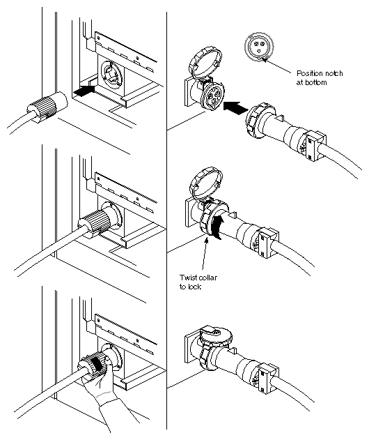
Insert the female end of the system power cable into the receptacle at the rear of the system chassis (see Figure 3-10). Secure the cable by turning the connector clockwise to engage the twist lock.
Connect the male end of the power cable to an AC power source using the appropriate receptacle, either a locking collar or a twist-lock connector (see Figure 3-10). Turn the locking collar on the keyed connector clockwise to engage the locating tabs on the AC outlet. Turn the twist-lock connector clockwise to secure it to the AC outlet.

Warning: See the Challenge/Onyx Site Preparation Guide for the system's power requirements.The Onyx rackmount workstation operates on 220-400 VAC. Use extreme caution when working around this voltage. Never install or remove power cords without first turning off the equipment. If the monitors and peripherals are equipped with voltage select switches, verify that they are set for the appropriate AC voltage.
Connect the power cords from the monitor(s) and additional peripherals to the appropriate three-pronged grounded outlets.
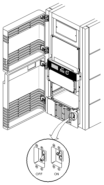
Turn on the system power switch (see Figure 3-11).
Turn on the monitors, followed by any attached peripherals..
Note: All internal storage devices are automatically powered up by the System Controller. Boot the system as described in “Booting the System.”
Boot your system by performing the following steps:
Power on the system, as described in the preceding section, “Powering On the System.”
Open the lower front door to the system chassis.
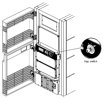
Insert the system key into the key switch, located to the right of the System Controller's display. Turn the key switch to the On position (see Figure 3-12).
Note: The System Controller begins the power-on sequence. The green power-on LED, located above the function buttons, lights to indicate that power has been applied to the system midplane. The amber fault LED then lights to indicate that power has been supplied to the System Controller. The fault LED goes out when the System Controller has successfully initialized and the power-on tests have completed.
After the bootmaster CPU has been selected, the system's progress can be monitored on the System Controller's display. Use the function buttons to select the Boot Status menu, and a series of status messages are displayed during a normal boot cycle (see Table 3-6).
Note: Do not press any of the front panel buttons until the “Boot Arbitration is Complete” message is displayed by the System Controller. Pressing the buttons before the bootmaster CPU is identified will abort the boot arbitration process. When the power-on tests have completed, you will see this message:
Starting up the system...
To perform System Maintenance instead, press <Esc>.
Table 3-6. System Controller Boot Status Messages
Boot Status Message
Message Description
BOOT ARBITRATION NOT STARTED
The system CPU boards have not begun the arbitration process.
BOOT ARBITRATION IN PROCESS
The system CPU boards are communicating to decide which one will be the bootmaster CPU.
BOOT ARBITRATION IS COMPLETE SLOT #xx PROC #yy
The chosen CPU has identified itself to the System Controller, and communication is fully established.
BOOT ARBITRATION INCOMPLETE FAULT NO MASTER
The system was unable to assign a bootmaster CPU.
BOOT ARBITRATION ABORTED
One of the front panel buttons was pushed while the System Controller was searching for a bootmaster.
To reconfigure your system or to list your system's hardware, press <Esc> within five seconds.
Note: If you don't press <Esc> within five seconds, the system will come up and display the desktop. If this happens, log in, shut down the system using the “System Shutdown” command from the System Maintenance menu, and then restart it when prompted. When the System Maintenance menu appears, type 5 to select “Enter Command Monitor.”
When the >> prompt appears, type hinv then press <Enter> to display the hardware inventory of your system.
Note: See the IRIX Advanced Site and Server Administration Guide for information on reconfiguring your system. Quit the Command Monitor by typing Exit at the >> prompt.
The System Maintenance menu reappears. Type 1 to select the “Start System” command. The system comes up and displays the desktop.
The basic IRIX operating system is factory-installed on your system disk. No software installation is required. If additional software is desired, it must be downloaded either locally (using a CD player) or downloaded remotely over the network. See the IRIX Advanced Site and Server Administration Guide for additional information about mounting and configuring drives. Refer to the IRIS Software Installation Guide for the steps required to download the software.
| Note: A copy of the IRIX operating system is supplied with the system on a compact disc (1/4-inch tape can be special-ordered). Place the CD or tape in a secure place in case you ever need to reinstall the operating system. |
The Video Out Panel is a feature of the VTX and RealityEngine2 graphics subsystems. The Video Out Panel is a software tool that allows you to selectively transmit screen displays and images to the composite or Super VHS (SVHS) monitor and VCR. For example, demos of 3-D graphics, or visual displays of mathematical functions that are displayed on the high-resolution 21-inch monitor, can be captured and displayed on the composite or SVHS monitor and recorded on a VCR.
With the Video Out Panel, you can control the video signals to the CMPST A and B and SVHS A and B ports. Pop-up menus allow you to select between NTSC and PAL video formats, standard or in-house video synchronization, and standalone or special genlock signals. An Options menu allows you to fine-tune the genlock delay, chrominance phase, chrominance color, and horizontal phase signals.
To start the Video Out Panel, type vo and press <Enter> in a text window in your WorkSpace™. The Video Out Panel Controls menu now appears on your screen (see Figure 3-13).
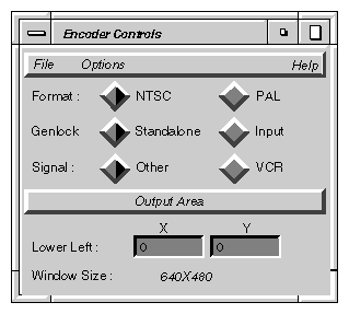
The Controls menu has buttons that select different video options. These options are described in Table 3-7.
Table 3-7. Options on the Controls Menu
Option | Function |
|---|---|
Format | NTSC or PAL. These two buttons select between the two most common composite video standards. You must select the correct format that matches your composite video monitor. Note: When you select a video format, the rest of the controls will default to the most appropriate setting for that video format. |
Genlock | Genlocking is used to synchronize to another video signal. This is normally set to Standalone. The Input setting is used with special “in-house” signals. |
Signal | Other or VCR. These buttons select the type of synchronization signal to be sent to the monitor/VCR. This should normally be set to Other. |
Output Area | Clicking this button causes a window to appear on the screen. By holding down the mouse button, you can move this window over your screen until it covers the display that you want to transmit or capture. |
Lower Left | As an alternative to the Output Area button, you can enter the lower left x and y coordinates in these boxes to position the output screen precisely. |
Window Size | This display shows the screen resolution for the video mode you have selected. It automatically shows the appropriate mode when you click NTSC or PAL. |
You can control the video signals through the Options menu. Click the Options field in the Controls menu to invoke the Options menu (see Figure 3-14).
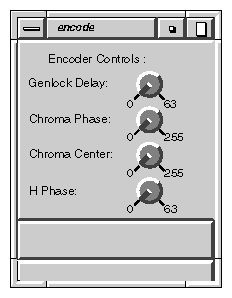
The Options menu has buttons that control the video signals through the ports. The buttons are controlled by the mouse. Place the cursor on the button, and click and hold down the mouse button. As you move the mouse in an arc, the button turns just like a rotating knob. The options are described in Table 3-8.
In most cases, the Options menu is not needed. For most uses, the default settings are perfectly suitable.
Table 3-8. Options on the Options Menu
Option | Function |
|---|---|
Genlock Delay | Genlocking is synchronized with another video signal. This control allows you to minutely control the advance or delay of the synchronization. The control cycles through a range of 0 to 63. |
Chroma Phase | Chrominance is a separate signal that contains color information. It is derived from the I and Q signals in the NTSC video format and from the U and V signals in the PAL video format. This control regulates the amount of light in each pixel comprising the R, G, and B signals. It is roughly analogous to the HUE control on a color television. It cycles through a range of 0 to 255. |
Chroma Center | This control is analogous to the TINT control of a color television. It controls the color saturation of the display and cycles through a range of 0 to 255. |
H Phase | This control regulates the horizontal sync, which is the lowest portion of the horizontal blanking part of the video signal. It provides a pulse for synchronizing video input with output and cycles through a range of 0 to 63. |
This section takes you through a sample session with the Video Out Panel. To start, let's assume that you have a graphic image or animation sequence running on the 21-inch high-resolution monitor. You should size the window in which the display is running so that it doesn't take up the entire screen.
Type the command vout and press <Enter>. The Controls menu appears.
Click either the NTSC or PAL button, depending on the video format of your monitor and VCR. Your choice here determines the default settings for the rest of the controls.
Now click the Output Area button. A black rectangle appears on the screen. The rectangle has the correct format, that is, aspect ratio, for either PAL or NTSC. This rectangle is much smaller than the full screen area because NTSC and PAL operate at a much lower resolution than your VTX or RealityEngine2 graphics system does.
Use the mouse to move this window. Move the cursor over the frame of the window and hold down the mouse button. You can now move the window over the portion of the image or animation that you wish to send to the composite monitor or VCR. If the image is too large to be captured in the window, resize the display window, then pull the black output window over the image again.
Once you have covered the display with the output window, you see the demo or image appear in the output window and also on your composite video monitor. If you have a VCR connected, you can begin recording immediately.
| Caution: The Video Out Panel captures images only when the high-resolution monitor is running at its default configuration of 1280 x 1024, or at the high resolution of 1600 x 1200. While other video resolutions are supported, the images do not appear on the composite or SVHS monitor. |
The system should be powered off only for routine maintenance or repair. You can power your system off in either of two ways:
Choose “System Shutdown” from the System menu.
Bring the system down from a shell.
Become superuser by typing /bin/su and pressing <Enter>.
Enter your superuser password, if prompted.
When you see the superuser prompt (#), type /etc/shutdown and press <Enter>.
A message similar to the following appears on the screen:
Okay to power off the system now.
Press any key to restart.
Turn off the power switches for the system and the peripherals in the following order:
Printer (if installed)
Monitors
Onyx system
Reset your system by turning the key switch on the System Controller to the Manager position. Use the scroll buttons to bring up the Reset menu. Press the Menu button to activate the menu, then press the Execute button to reset the system. If the system is completely unresponsive, use only the Reset function, not the main power switch, to reboot your system. If your system responds to input, use the shutdown option in the System Maintenance menu or the halt command.