- American National Standards Institute (ANSI)
The United States standardization body. ANSI produces documents that describe standards for information systems and input/output interfaces such as FDDI. ANSI is a member of the International Standards Organization (ISO).
- ANSI
See American National Standards Institute.
- attenuation
The weakening or diminishing of signal strength that can result in a loss of data.
- bandwidth
The range of frequencies that can be used for transmitting information on a channel, equal to the difference in hertz (Hz) between the highest and the lowest frequencies available on that channel. Bandwidth indicates the transmission capacity of a channel; the larger the bandwidth, the greater the amount of information that can pass through a circuit.
- beacon process
A fault isolation process that is initiated after a ring fault occurs and the claim process fails. Stations within the ring send beacon frames to isolate the fault.
- bypass
The ability of a node to isolate itself optically from the ring while maintaining the integrity of the rest of the ring.
- canonical order
In the computer world, the term bit order is analogous to the order for reading a flow of letters in text. Canonical order is somewhat like reading across the page from left to right, but reading each word from right to left. So, the characters TIME WAR would be read as “emit raw.” To compare this to a very different ordering, see FDDI order.
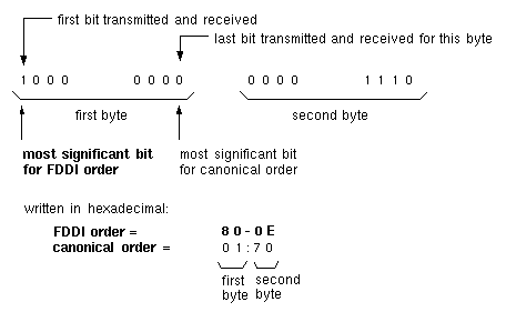
In more technical terms, canonical order is a method for representing the 48-bit (6-byte) sequences used for addresses in FDDI. This method considers the first bit transmitted within each byte to be the least significant bit, as illustrated in Figure Gl-1. For example, the sequence <1 followed by 0, 0, 0> is represented as 1 in decimal (not as 8). This is the ordering traditionally used for Ethernet addresses and is bit-swapped within each byte with respect to FDDI ordering. For the bytes themselves, the first transmitted byte is considered to be the most significant byte.
The SMT commands represent each byte of a canonically ordered FDDI address as a hexadecimal value (two hexadecimal characters) separated by a colon (:), for example, 08:00:69:a4:0c:d0. See also FDDI order.
- CDDI
See copper distributed data interface.
- CEM
See configuration element management.
- CFM
See configuration management.
- cladding
The low refractive index material that surrounds the core of an optical cable.
- claim process
A process in which stations bid for the right to initialize the ring.
- CMT
See connection management.
- CON
See concentrator.
- configuration element management (CEM)
The portion of connection management (CMT) that manages the configuration of a port and, if present, its MAC. There is one instance of this functionality for each port on a station or concentrator.
- concentrator (CON)
An FDDI node that has additional ports beyond those required for its own attachment to an FDDI network. These additional ports (type M) are for attaching other FDDI nodes (including other concentrators) in a tree topology.
- configuration management (CFM)
The portion of the station management that manages the configuration of the station's MAC and PHY entities.
- connection management (CMT)
The portion of the FDDI SMT that manages the operation of the physical layer. CMT functionality is divided into three areas: physical connection management (PCM), configuration element management (CEM), and entity coordination management (ECM). CMT performs the following:
monitors the primary and secondary ring
isolates and wraps around noisy or quiet links
prevents stations from entering the ring in an illegal topology
verifies when a faulty link has been fixed and unwraps the ring
- connector plug
A device used to terminate an optical signal transmission cable. The connector plug is the male half of an optical signal transmissions cable connection. Plugs connect to receptacles. See also media interface connector, straight tip connector.
- connector receptacle
A device used to terminate an optical signal transmission cable. The connector receptacle is the female half of an optical signal transmissions cable connection. Receptacles connect to plugs. See also media interface connector, straight tip connector.
- copper distributed data interface
An FDDI-like protocol that uses copper cabling (either shielded or unshielded twisted pair) instead of fiber optic cabling for attaching nodes to concentrators.
- core
The central transmission area of a fiber. The core always has a refractive index higher than that of the cladding. The core acts as a wave guide and confines the signal.
- counter-rotating
An arrangement in which the light signal within each loop of a dual ring travels in opposite directions.
- DA
See destination address.
- DAS
See dual-attachment station.
- decibel (dB)
A standard unit that uses a logarithmic scale for expressing transmission gain or loss and relative power levels.
- destination address (DA)
The address of the station to receive the data. Consists of 4 (16-bit address) or 12 (48-bit address) symbols. A physical connection to the ring that performs the conversion from optical to electrical signals, symbol detection and decoding, and error detection and line state detection.
- dotted decimal notation
A way of representing a 32-bit (4-byte) Internet address in ASCII. Each byte of the address is represented as a decimal number (ranging in value from 0 to 255). Bytes are separated by a dot (.). For example, 126.52.4.89. See also Internet address.
- downstream
The direction of an optical signal's flow within the ring.
- dual-attachment station (DAS)
An FDDI station that offers two connections (attachments) to the FDDI ring. The two connections can connect to the primary and secondary rings, or the two can be attached to a concentrator for a dual-homed configuration.
- dual-fiber cable
A type of optical fiber cable that has two single-fiber cables enclosed in a jacket of extruded PVC, with a ripcord for pulling back the jacket to access the fibers.
- dual-homed
A DAS configuration in which both ports are connected as S-type ports to a concentrator. Port A is connected to one M-type port and B is connected to a different M-type port on the same or a different concentrator. This configuration provides a backup interface if one port should fail. Synonym: tree connection with redundancy.
- dual ring
An FDDI ring configuration with two separate loops (rings) of fiber optic cable. It is common for one loop to be the main (primary) ring and the other to be used as a backup. In this configuration, the ring can wrap to reestablish communication when there are problems with the primary ring. It is also possible to configure both rings as main (data carrying) networks.
- ECM
See entity coordination management.
- entity coordination management (ECM)
The portion of CMT that manages the media interface to the FDDI network, which includes coordinating the activity of all of the PHYs associated with that physical attachment and controlling the optional optical bypass function within the station. There is only one instance of this functionality on a station or concentrator.
- Ethernet order
See canonical order.
- FDDI
See fiber distributed data interface.
- FDDI order
In the computer world, the term bit order is analogous to the order for reading the flow of letters across a page of text. FDDI order is somewhat like reading from left to right, as English speakers normally do. Thus, the characters TIME WAR would be read as “time war.” To compare FDDI order to a very different ordering, see canonical order.
In more technical terminology, FDDI order is a method for representing the 48-bit (6-byte) sequences used for addresses in FDDI. This method considers the first transmitted bit within a byte to be the most significant bit, as illustrated in Figure Gl-2. For example, the sequence <1 followed by 0, 0, 0> is represented as 8 decimal. This is FDDI's native ordering and is bit-swapped within each byte with respect to canonical (or Ethernet) order. For the bytes themselves, the first transmitted byte is considered to be the most significant byte (the same as for canonical order).
The SMT commands represent each byte of an FDDI address in FDDI order as a hexadecimal value (two hexadecimal characters) separated by a dash (-), for example, 10-00-96-25-30-0b. See also canonical order.
- fiber distributed data interface (FDDI)
A fiber distributed data interface that is a 100 Mbps standard for fiber optic communications made up of two counter-rotating rings of message traffic.
- fiber optic cable
A type of communications cable constructed of material (for example, glass) that allows an optical signal (light) to travel through it. Fiber optic cable currently is available in two types: multimode and single-mode.
The inside diameter, or pipe, of multimode fiber optic cable is big enough so that light “bounces off the walls” in a number of ways as it proceeds down the fiber. Each of the possible paths is referred to as a mode that takes a slightly different time to travel down the pipe. The existence of the multiple modes causes intersymbol interference.
Single-mode fiber optic cable is narrower than multimode, so the transmitted signal bounces less. Only one mode (straight down the center) maintains its power and is low loss. The other modes quickly dissipate as light moves down the fiber.
The larger, multimode fiber optic cable (typically 62.5 micron internal diameter) is easier to launch a signal into. The interference, rather than the loss of power or spectral purity, limits the distance for a given bit rate, so multimode fibers are most often driven with inexpensive light-emitting diodes (LEDs).
The smaller, single-mode fiber (typically 50 micron internal diameter) is harder to couple power into. However, since there is only one mode, the light can travel much farther without successive bits interfering with each other—or, equivalently, a higher bit rate can be supported at a given distance. To achieve its higher potential, single-mode fiber is usually (but not always) driven with expensive semiconductor lasers rather than LEDs.
- fiber optics
A technology whereby signals are transmitted over an optical waveguide medium through the use of light-generating transmitters and light-detecting receivers.
- frame
A protocol data unit (PDU) transmitted between cooperating MAC entities on a ring. See also protocol data unit. The nine fields of the FDDI frame and the number of symbols used by each field are illustrated in Figure Gl-3: I = idle; SD = starting delimiter; FC = frame control; DA = destination MAC address; SA = source MAC address; data = user data; FCS = frame check sequence; ED = ending delimiter; FS = frame status.
- frame class
Identifies the general function of the frame. SMT defines eight frame classes, listed below:
- frame type
Defines the specific purpose of the frame. SMT frame types are Announcement, Request, and Response. Announcement communicates information; Request asks the targeted (destination) SMT to provide an answer; Response is the answer to a Request frame. Each SMT frame class supports one, two, or three frame types.
- frequency
The number of cycles completed by a signal in 1 second, expressed in hertz (Hz). For example, 5000 cycles per second is expressed as 5000 Hz (or 5 kHz).
- gateway
A computer that, in addition to doing all the tasks that a router performs, supports conversion (translation) from one network's protocols to the other's. For example, an FDDI/Ethernet gateway converts 4500-byte FDDI packets into 1500-byte Ethernet packets whenever packets originate on the FDDI ring and require routing (forwarding) to a destination on the Ethernet network. See also router.
- hostname
The user-friendly name assigned to a system. The hostname is specified in the /etc/sys_id file. A system's hostname can be displayed with the hostname command.
- IEEE order
See canonical order.
- interchannel isolation
The ability to prevent undesired optical energy from appearing in one signal path as a result of coupling from another signal path, thus eliminating crosstalk.
- International Standards Organization (ISO)
The international standardization body; ANSI represents the United States as a member of ISO.
- Internet address
Also called IP address. A globally unique 4-byte (32-bit) number used by the Internet Protocol (IP or TCP/IP) software to identify computers (or more accurately, computers' network connections). As the well-quoted dictum says: “In the IP world, hosts do not have addresses, network interfaces do.” One computer (host) can have one or more IP addresses; each physical network connection for a host must have at least one unique IP address.
Internet addresses come in a number of classes; the major classes are A, B, and C. All IP addresses have three parts: class identifier, network identifier, and host identifier. The number of bits used to represent each part depends on the address' class, as described below:
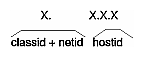
Class A addresses use one bit (bit 0) for class identification, 7 bits for network identification, and 24 bits for host identification.
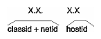
Class B addresses use 2 bits (bits 0 and 1) for class identification, 14 bits for network, and 16 for host.
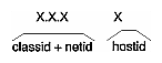
Class C addresses use three bits (bits 0 to 2) for class identification, 21 for network, and 8 for host.
The class plus network identification parts are commonly referred to as the “network address,” while the class, network, and host identification parts are referred to as the “host address.” For example, the network address for a device with an IP (or host) address of 206.2.71.198 is “net 206.2.71.” IP addresses are usually represented in ASCII digits 0 to 9 in dotted decimal notation (for example, 126.13.69.237). Table Gl-1 shows the maximum world-wide number of networks that are possible for IP addresses. Table Gl-1 also shows how many hosts can share any single network address.
Table Gl-2 summarizes the ranges of valid addresses within these three classes.
To ensure global uniqueness, network addresses (or blocks of them) are assigned, by the Network Information Center, to requesting organizations. The network administrator for each organization allocates the individual addresses (host addresses within the assigned blocks) to specific devices. Local network administrators are responsible for ensuring that two devices at the same site do not use the same address. See also dotted decimal notation.
- IP address
See Internet address.
- ISO
See International Standards Organization.
- JK
The nondata symbol pair that identifies the start of a frame. See also symbol.
- least significant
The item in a sequence that, by its placement within the sequence, makes the least difference in the value. For example, in the decimal number 209, nine is the least significant digit because it represents ones while the other digits represent larger values (tens and hundreds). See also most significant.
- line state
One of several characteristic patterns of bits or symbols transmitted on an FDDI fiber. See also symbol.
- LLC
See logical link control.
- load
The amount of traffic on the ring.
- logical ring
The set of MACs (for example, FDDI stations) serially connected, thus forming a single ring. An unwrapped, fault-free FDDI ring provides two logical rings.
- logical link control (LLC)
Local area network protocols in the lower layers of the OSI model. See also Open Systems Interconnection.
- MAC
See media access control.
- management information base (MIB)
A database of FDDI station and ring information. Each Station Management (SMT) module manages its own MIB; however, in order to manage the ring, SMTs share much of the MIB information with each other. Each MIB object (item of information) has a set of attributes, including read and write permissions. FDDIXPress provides the /usr/etc/smtstat command to display MIB information.
- media access control (MAC)
Local area network protocol functions corresponding to the OSI data link layer (layer 2). MACs provide the following:
on transmission, assemble data into a frame with address and error-detection fields
on reception, disassemble frame, perform address recognition and error detection
manage data link layer communication
- media interface connector (MIC)
A type of connector that provides an interface (connection) between FDDI cables. Each MIC contains two fiber optic fiber lines: one for transmit and one for receive.
- MIB
See management information base.
- MIC
See media interface connector.
- MIC receptacle
The fixed or stationary half of an optical signal transmissions cable connection attached to FDDI. Receptacles mate with plugs. See also connector receptacle.
- most significant
The item in a sequence that, by its placement within the sequence, makes the most difference in the value. For example, in the decimal number 209, two is the most significant digit because it represents hundreds while the other digits represent smaller values (tens and ones). See also least significant.
- neighbor
A term that refers to the two functioning stations on either side of an FDDI station. A neighbor station is the immediate next station on a logical ring when viewed from the station in question. A neighbor can be either upstream or downstream. See also upstream, downstream, logical ring.
- neighborhood information frame (NIF)
The neighborhood information frame is used by a station for periodic announcement of its address and basic station description.
- network address
A unique, nonphysical address that identifies a local area network. The format for this address varies depending on the address family (for example, OSI, Internet). For the Internet (IP or inet) family, the network address is an IP address in which that portion commonly referred to as the netid is followed by a hostid portion of zero. For example, a Class A address of 125.0.0.0 (dotted decimal notation), a Class B address of 191.252.0.0 (dotted decimal notation), and a Class C address of 203.27.190.0 are all network addresses.
Note: In some environments, the definition and usage of the term network address is quite different from this definition.
The OSI family's equivalent to the IP address is the NSAP address as defined in ISO8348, not the SNPA.
- network connection name
A user-friendly name associated with a specific network interface. Network connection names are specified in the /etc/hosts file. The network connection name for the primary network interface is the system's hostname. (See hostname.) By convention, a system's other network connection names include the system's hostname. For example, a host by the name of mickey with two network connections might have its FDDI interface associated with the network connection name mickey, while its Ethernet interface is associated with the name gate-mickey.
- Network Information Center
The central authority that assigns blocks of Internet Protocol (IP) addresses to worldwide public and private organizations. The current address for this organization is Government Systems, Inc., Attn: Network Information Center, 14200 Park Meadow Drive, Suite 200, Chantilly, VA 22021 (at telephone 1-800-365-3642). See also Internet address.
- NIF
See neighborhood information frame.
- node
A generic term referring to an active device (station or concentrator) on an FDDI ring. Each node has one (and only one) SMT module managing it. A node can have zero or multiple MACs, PHYs, and PMDs.
- octet
A data unit composed of eight ordered bits; octet is a synonym for byte. A pair of data symbols is represented in one octet.
- Open Systems Interconnection (OSI)
The OSI model is a standard for computer communications protocols and the implementation of these protocols. The model is a product of International Standards Organization (ISO) and specifies a seven-layer architecture.
- optical bypass switch (OBS)
A device that can be connected between a dual-attachment station and the dual ring. If the station fails, is powered off, or is physically removed, the OBS prevents the ring from wrapping by directing the signal back onto the ring, thus bypassing the station. The station's two neighbors will notice that their upstream or downstream neighbor has changed, but the signal continues to loop around the ring, so no wrap occurs.
- OSI
See Open Systems Interconnection.
- path test
A self-test performed by an FDDI node's own CMT to verify that its connection to the ring is performing correctly. The path test is one part of the trace function.
The path test includes the following items:
verification that the MAC can resolve the beacon and claim process
loopback verification of the PHY's functionality
verification of accessibility of all data paths at the node
confirmation of the parameters given to the MAC
- PCM
See physical connection management.
- PDU
See protocol data unit.
- PHY
See physical layer protocol.
- physical connection management (PCM)
The portion of connection management (CMT) that manages a physical connection between the PHY being managed and another PHY, likely an adjacent (neighbor) station on the ring.
- physical layer protocol (PHY)
The layer that performs the clock recovery and serial-to-parallel (receive) or parallel-to-serial (transmit) conversion of data between the transmission medium and the MAC entity.
- physical layer medium dependent protocol (PMD)
The medium that specifies the optical-to-electrical conversion mechanism to conform to FDDI.
- PMD
See physical layer medium dependent.
- port
The physical location where a computer's signals pass through to a peripheral device or a communications network medium (cable). In FDDI, there are four types of ports: A, B, S, and M. Ports A and B are both used for a dual-attachment configuration; port S is used for a single-attachment configuration; M ports are found only on concentrators. Each port has both an incoming (reception) line and an outgoing (transmission) line; however, in some configurations, only one line is in use.
- primary ring
The main transmission ring within a dual ring. See also DAS, ring, secondary ring.
- protocol data unit (PDU)
The unit of data transfer between communicating peer layer entities. It may contain control information, address information, data, or any combination of the three. The FDDI PHY PDUs are code groups such as frames and tokens. See also frame.
- receive
The action of a station accepting a token, frame, or other symbol sequence from the incoming medium.
- receiver
An electronic circuit that converts an optical signal to an electric logic signal.
- repeat
The action of a station in receiving a token or frame from the adjacent upstream station and simultaneously sending it to the adjacent downstream station.
- ring
Two or more stations that pass information sequentially through a physical medium (cable). Each station examines all information on the physical medium, copies information sent to it, and returns the information to the cable where the originating station can read it.
- ring management (RMT)
The portion of connection management that monitors the MAC. It provides a trace mechanism to handle beaconing and also detects duplicate addresses on the ring.
- RMT
See ring management.
- router
A computer that routes (forwards) packets between two or more networks and is capable of discovering (or maintaining) routes to distant network destinations. In the simplest situation, a router with two network connections moves from network 1 to network 2 all of the packets that have been transmitted on network 1, but are destined for a host on network 2, and vice versa. In cases in which the destination host is located on a network to which the router is not physically attached, the router sends the packet to the next router along the route; and that router passes the packet to another router, until the packet can be delivered directly to the specified destination host. In OSI terminology, a router is an Intermediate System supporting network layer forwarding.
- SA
See source address.
- secondary ring
The backup ring used when a fault occurs on the primary ring. See also primary ring.
- SIF
See status information frame.
- single-attachment station (SAS)
A station that offers a single connection (attachment) to the FDDI network.
- SMT
See station management.
- source address (SA)
The address of the station that sends a frame. The address consists of 4 symbols (16-bit address) or 12 symbols (48-bit address).
- station
An addressable node on an FDDI network capable of transmitting, repeating, and receiving information. A station has exactly one SMT, at least one MAC, at least one PHY, and at least one PMD.
- station management (SMT)
One of the FDDI standards. The entity within a station that monitors station activity, exercises overall control of station activity, and manages the FDDI ring. The SMT module controls and manages the station's processes at the various FDDI layers. It also works cooperatively with other SMT modules to manage the ring. SMT provides services such as fault isolation and recovery for the ring, maintenance of the local station's MIB, control over station insertion and removal from the ring, and configuration management.
- station ID
An 8-byte (64-bit), site-configurable number used by SMT modules to identify and reference FDDI stations. This number is used only for reporting status information. The FDDIXPress SMT daemon, by default, creates the station ID from the station's MAC address. The six bytes of the MAC address (in canonical order) occupy the lower six bytes of the station ID and the upper two bytes are set to zero.
- status information frame (SIF)
Status information frames are used to request and provide, in response, a station's configuration and operating information.
- straight-tip (ST®)connector
An optical fiber connector used to join single fibers together.
- symbol
The smallest signaling element used by the data link layer. The FDDI symbol set consists of 16 data symbols and 8 control symbols. Each symbol corresponds to a specific sequence of 5 bits transmitted by the physical layer on the optic cable that is seen by software as a 4-bit sequence. (The 4-bit to 5-bit conversion, and vice-versa, is done by hardware.)
- target token rotation time (TTRT)
The amount of time a station bids in the claim process. The station whose claim indicates that it has the lowest TTRT wins the claim process. This TTRT value is then used by all stations on the network for setting TTRT.
- token
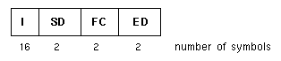
A packet that is the explicit indication of the right to transmit on a shared medium. On a token ring, the token circulates sequentially through the stations on the ring. At any time, it may be held by zero or one station. The format for the FDDI token is illustrated in Figure Gl-4. The FDDI token has four fields: I = idle; SD = starting delimiter; FC = frame control; ED = ending delimiter. The illustration indicates the number of symbols used for each field.
- token ring
A set of stations serially connected by a transmission medium (cable) to form a closed loop.
- token rotation time (TRT)
The maximum time that a token needs to make a complete circuit around the ring.
- trace
An RMT function that attempts to provide ring recovery when there is a stuck (continuous) beacon condition on the ring. The trace causes all stations and concentrators upstream from the tracing SMT to leave the ring and perform a Path Test. When the stuck device is isolated, the ring is wrapped so as to exclude the stuck device.
- transmit
The action of a station generating a frame, token, or control sequence and placing it on the medium to the next station.
- transmitter (optical)
An opto-electronic circuit that converts an electrical logic signal to an optical signal.
- tree
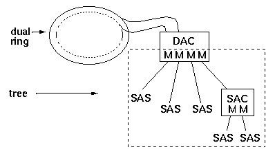
A physical topology consisting of a hierarchy of master-slave connections between a concentrator and other FDDI nodes (including subordinate concentrators) as illustrated by the dotted enclosure in Figure Gl-5.
- TRT
See token rotation time.
- trunk
A physical loop topology, either open or closed, employing two optical fiber signal paths, one in each direction (that is, counter-rotating), forming a sequence of peer connections between FDDI nodes. When the trunk forms a closed loop, it is sometimes called a trunk ring.
- TTRT
See target token rotation time.
- upstream
Opposite from the direction of the optical signal's flow within a ring.
- wrap
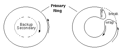
A condition in which the primary ring loops to (is connected to) the secondary ring. Wraps occur when there is a fault on the primary ring, as illustrated in Figure Gl-6. The fault or break in the primary ring prevents the optical signal from completing the loop around the ring, thus stopping all communication. Wrapping reestablishes the loop and allows communication to continue. When a ring is wrapped, one or more ports have been left out of the ring.


NIF | neighbor information frames |
SIF | status information frames |
ECF | echo frames |
RAF | resource allocation frames |
RDF | request denied frames |
SRF | status report frames |
PMF | parameter management frames |
ESF | extended service frames |
Table 32. Maximum Networks and Hosts Possible for IP Addresses
Class | Maximum Number of | Maximum Number of Hosts Possible for Each Network Address |
|---|---|---|
A | 127 | 16,777,213 |
B | 16,383 | 65,533 |
C | 2,097,151 | 253 |
Table 33. Internet Address Ranges
Class | Bit Usage Within Address | Smallest Non-Broadcast Valid Address | Largest Valid
Non-Broadcast |
|---|---|---|---|
A |
 | 1.0.0.1 | 126.255.255.254 |
B |
 | 128.0.0.1 | 191.255.255.254 |
C |
 | 192.0.0.1 | 223.255.255.254 |